> ## Documentation Index
> Fetch the complete documentation index at: https://docs.ntop.com/llms.txt
> Use this file to discover all available pages before exploring further.
# How to run a flow analysis
## Summary:
Ready to dive into fluid simulation with nTop? Learn how to perform a fluid analysis.
## Applies to:
* nTop 5.23 or later, as this is when nTop Fluids was introduced.
## Procedure:
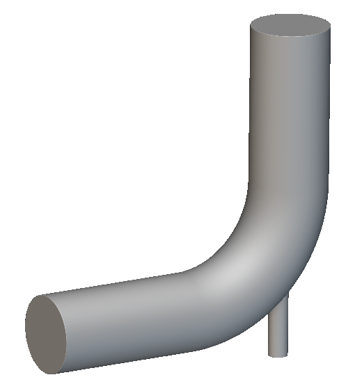
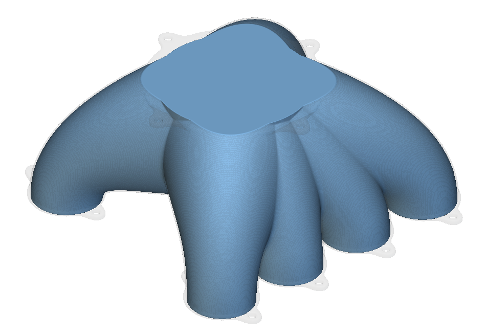
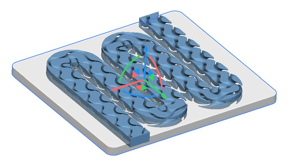
Before we start, please ensure you have generated the Fluid Geometry.
* Fluid Geometry: Have an implicit body that defines your internal fluid domain.
* For example, this could be a manifold's negative space, the heat exchanger's internal channels, or any other part through which fluid will flow.
| Pipes | Manifolds | Cold plates |
 |  |  |
1. Review the Fluid Geometry. For this example, we are starting with CAD Geometry, but you can also create your fluid geometry using Modeling blocks in nTop.
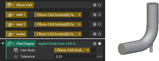
2. Add a **Flow Analysis** block
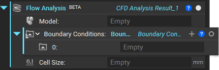
2. We need to add a **Simulation Model** (Virtual Model overload) as the Model input of the Flow Analysis block. You'll use its "Virtual Model" overload for flow analysis.
A Virtual Model is designed for simulations that don't require traditional body-fitted meshing in nTop, like LBM-based CFD. It acts as a container for your simulation setup.
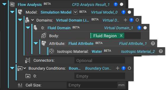
* * Add a **Fluid Domain**: This block defines the region where the fluid flow will be simulated. You'll input your implicit body representing the fluid volume here.
* Add a **Fluid Attribute**: This block assigns material properties to your Fluid Domain. You'll specify the type of fluid using the **Isotopic Fluid Property** block (e.g., Water, Air) and its relevant characteristics (Density, Kinetic Viscosity). **Water** and **Air** blocks are directly available for use.
*Note: These blocks will differ from traditional Structures setup in nTop as they are tailored for methods like LBM, streamlining the setup for complex implicit geometries.*
3. Once we have added the Domain, we need to move the input of the Flow Analysis block's Boundary Conditions ([How to use a CAD Face in a boundary condition](/help-articles/knowledge-base/structures/how-to-use-a-cad-face-in-a-boundary-condition)). For our example, we will use two **Velocity** Inlets and one **Pressure** Outlet.
*Note: To run **Flow Analysis**, you need at least one pressure and one velocity boundary condition, and outlets need to have the same pressure value.*
**Every remaining boundary not defined as a Velocity or Pressure boundary is set to a no-slip boundary condition.**
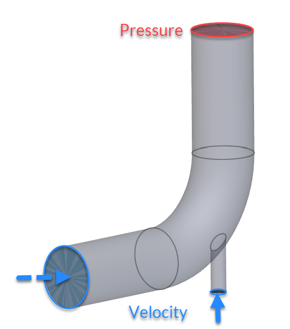
| **First Inlet (Velocity)** 1. Drag in a **Velocity** block 2. Switch to the CAD overload and then select the Inlet Face 1 3. Enter the Velocity Vector value (0,10,0) | **Second Inlet (Velocity)** 1. Drag in a **Velocity** block 2. Switch to the CAD overload and then select the Inlet Face 2 3. Enter the Velocity Vector value (10,0,0) | **Outlet (Pressure)** 1. Drag in a **Pressure** block 2. Switch to the CAD overload and then select the Outlet Face 3. Enter the Magnitude of 0 Pa. |
| --------------------------------------------------------------------------------------------------------------------------------------------------------------------- | ---------------------------------------------------------------------------------------------------------------------------------------------------------------------- | --------------------------------------------------------------------------------------------------------------------------------------------------- |
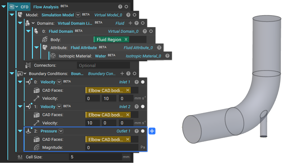
4. The last input of the **Flow Analysis** block is Cell Size. This is the size of the cells used to create a Cartesian grid across your domain. For this example, we can use a value of 5mm.
**Tips on Cell Size:**
* The flow analysis uses a uniform Cartesian mesh, defined by a single parameter: Cell Size.
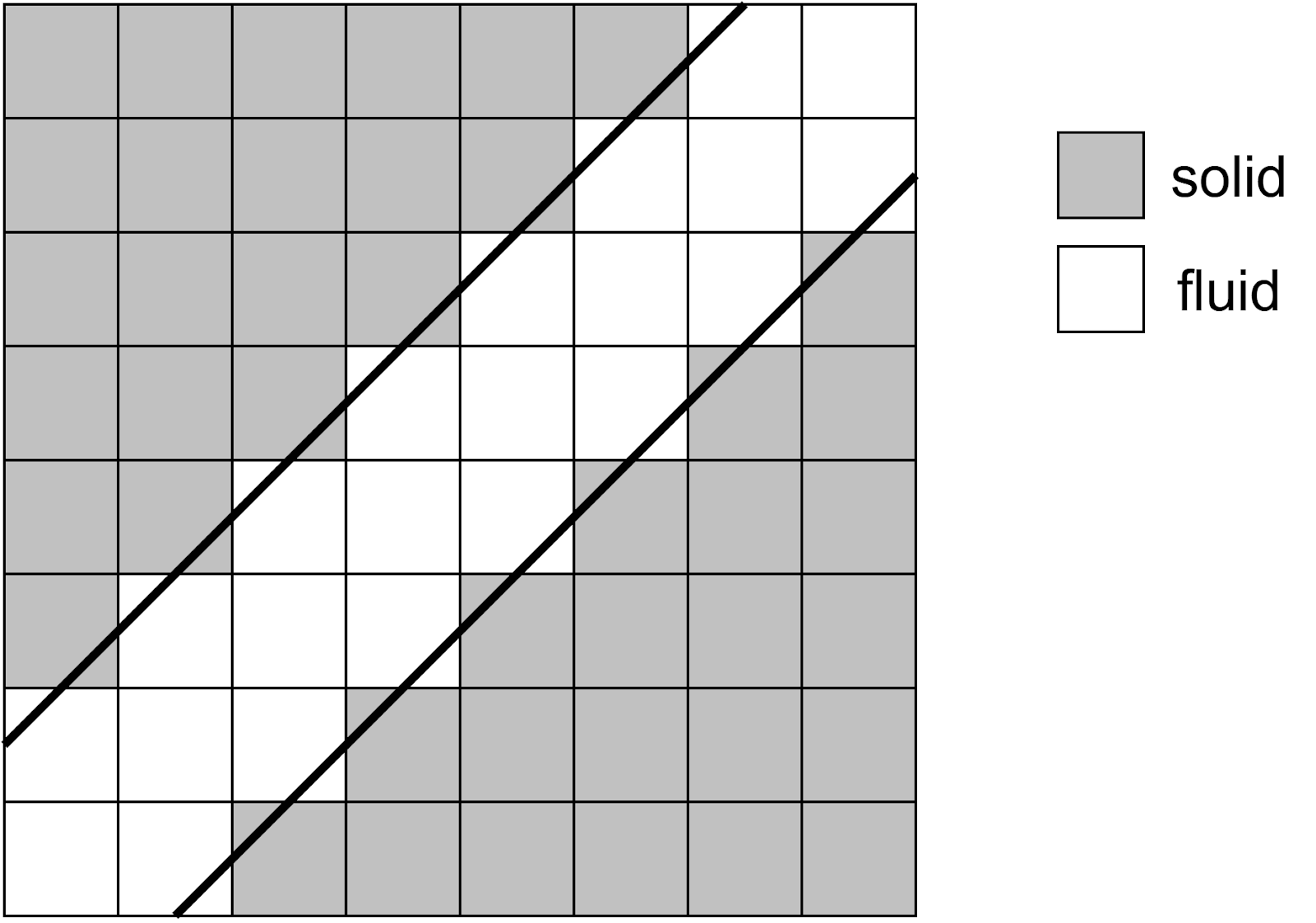
* For quantitative results, use at least seven cells to resolve the smallest flow diameter, gap, or hole; for turbulent boundary layers, 20+ cells are recommended.
* At least three cells should resolve the smallest flow features for qualitative results. Smallest Flow Feature
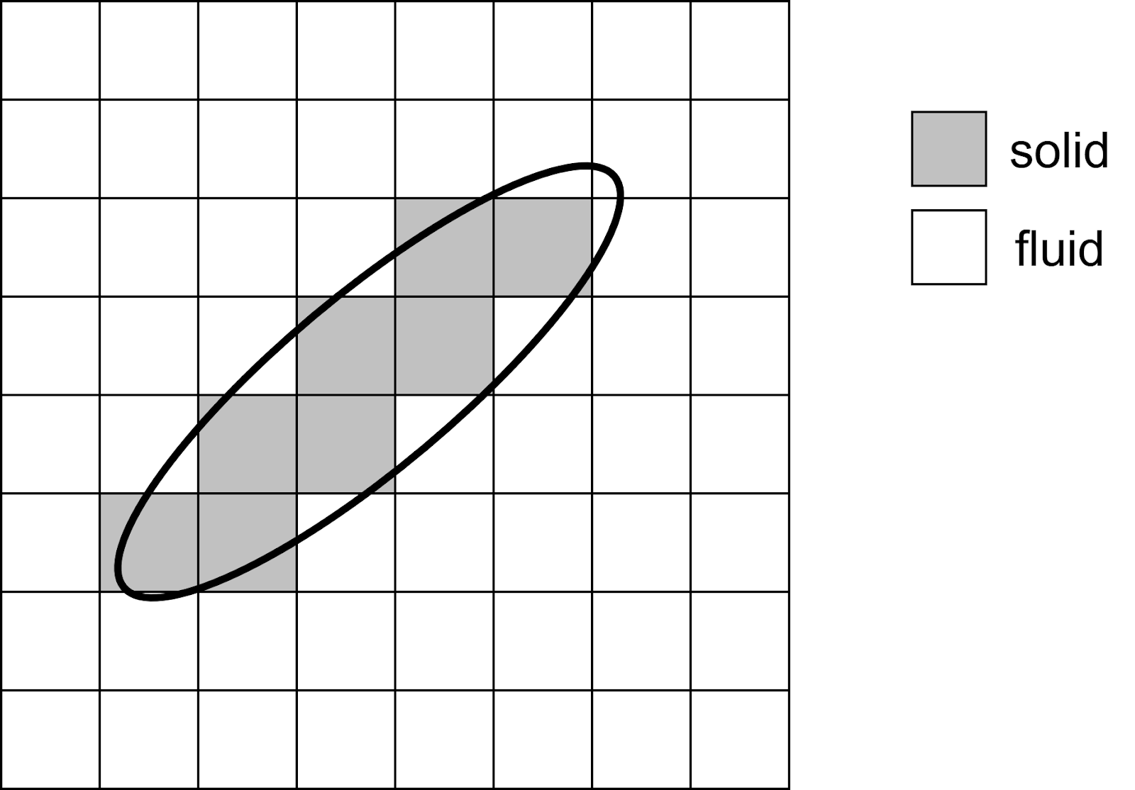
* Solid structures should be resolved with at least two cells.
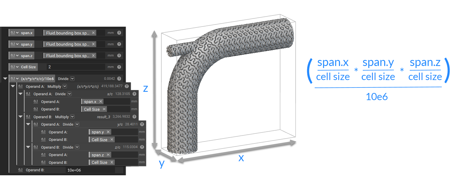
* Memory estimation: Ten million cells require approximately one GB of dedicated GPU memory. The following calculation provides a conservative estimate of the required GPU memory (in GB)
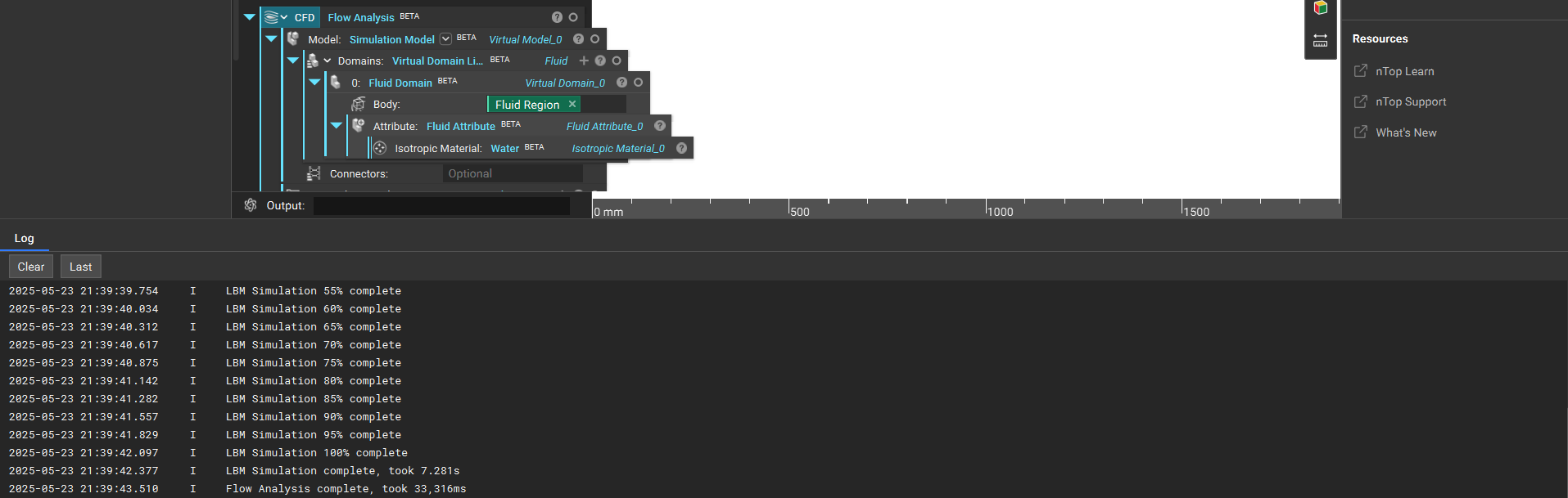
5. While the **Flow Analysis** is running, you can see the progress updated in the Bottom Panel (Ctrl +3)
7. Once the Flow Analysis is completed, we can review the results. Isolate the **Flow Analysis** block to visualize the results.
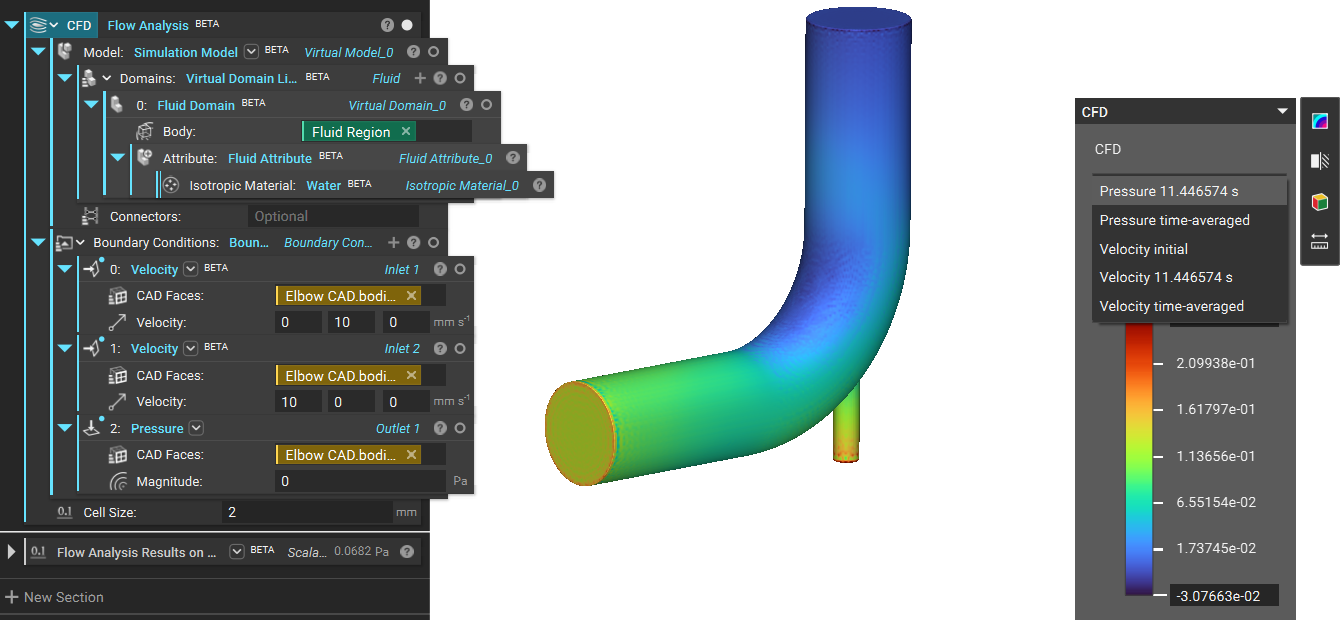
When you toggle the Pressure option on the HUD, you can switch between different available results such as Velocity and Pressure.
The default Display Mode is Domain, but you can switch it to visualize Streamlines in the Display tab of the Right Panel.
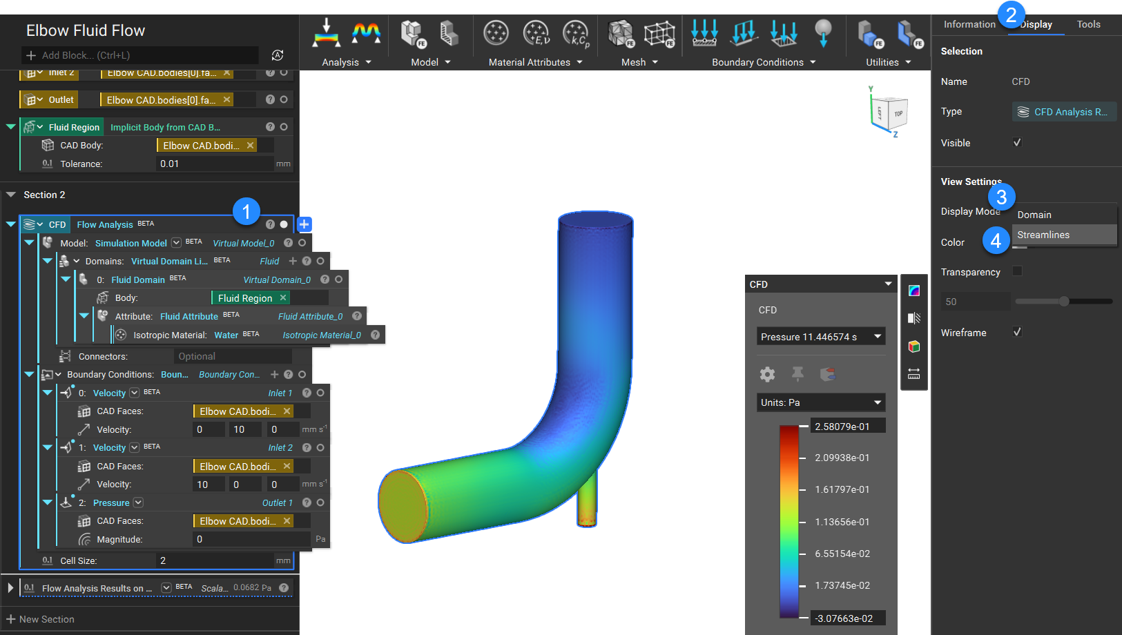
## Visualized results of an example flow analysis with the display set to Streamlines
**Streamline Settings:**
Seed Count: This input allows you to control the number of seed points. Increase the number for a denser, streamlined plot.
Specify Seed: When you check this input, you can place a Sphere with Center \[mm] and Radius \[mm] to specify the region where you want to select the seed points.
**Flow Analysis Results on Boundary**
We have a **Flow Analysis Results on Boundary**, which allows you to calculate the average value of the Flow Analysis results, such as Velocity and Pressure, on the selected Boundary. Like other analysis blocks in nTop, **Flow Analysis** block will have access to all the underlying fields from which you can calculate values.
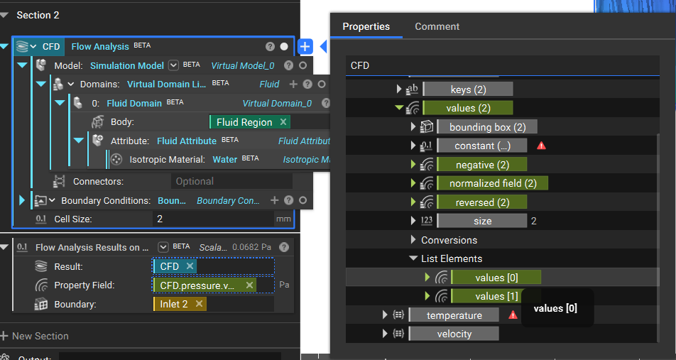
That's it: you have completed your flow analysis.
## Attachment:
* [Flow Analysis](https://files.learn.ntop.com/Support%20Article%20Example%20Files/Knowledge%20Base/Fluids/flow_analysis.ntop)
## Keywords:
*analysis fluid flow cfd document fluids*