> ## Documentation Index
> Fetch the complete documentation index at: https://docs.ntop.com/llms.txt
> Use this file to discover all available pages before exploring further.
# How to run an aircraft flow analysis
### **Objective**
This article explains the process for setting up and running a GPU-accelerated Computational Fluid Dynamics (CFD) simulation using the **Aircraft Flow Analysis** block to obtain aerodynamic performance data, including pressure, velocity fields, and surface forces.
### **Applies to:**
* Calculating lift, drag, and moments on wings, fuselage sections, or complete aircraft assemblies.
### **Procedure:**
***System Requirements:** Requires an **NVIDIA GPU** for flow analysis.*
*Note: This capability is currently only applicable to subsonic flows (speeds up to Mach 0.7).*
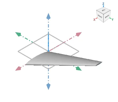
1. **Prepare and Orient the Geometry:** Ensure your aircraft geometry is represented as an **Implicit Body** and is correctly oriented:
* Flow direction must be aligned with the positive **X-axis**.
* Starboard/right wing direction must be aligned with the **Y-axis**.
* Lift direction must be aligned with the **Z-axis**.
2. Add the **Aircraft Flow Analysis** Block: Insert the block from the Fluids > Analysis section of the ribbon.
* Drag and drop your Implicit Body to the **Aircraft Body** input.
* **Define Flow Parameters:** Input the required freestream conditions and cell size:
1. Set the **Mach number** (required).
2. Set the **Temperature** (default is 288.15 K) and **Pressure** (default is 101325 Pa).
3. Input the desired **Angle of Attack** (in degrees).
4. Define the **Cell Size**.
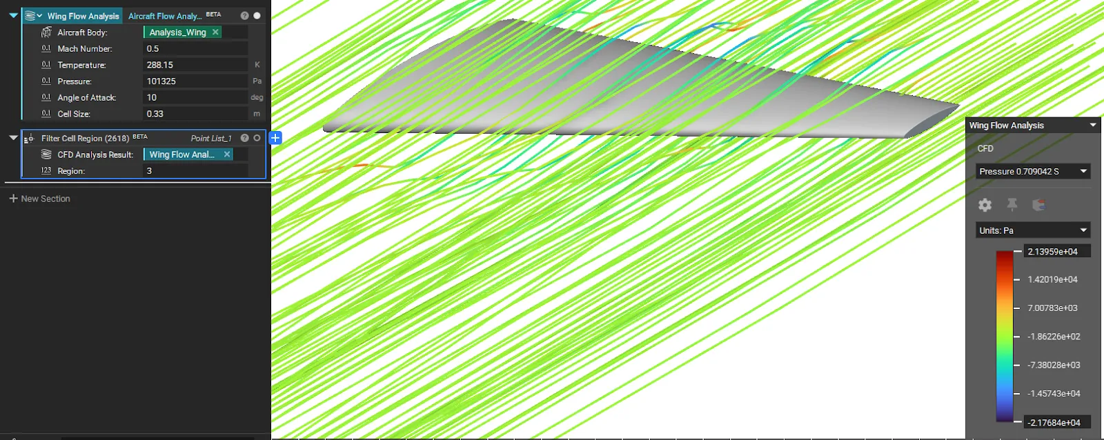
*Note: Smaller cell sizes increase fidelity but require significantly more computation time.*
3. **Analyze Results:** Run the block. The simulation will run until it reaches a steady state and output a **CFD Analysis Result**, which you can use for post-processing, visualization, and extracting force data.
* **Check Boundaries:** Review the boundary conditions set by the block in the properties panel to confirm the velocity inlet and pressure outlet are correct.
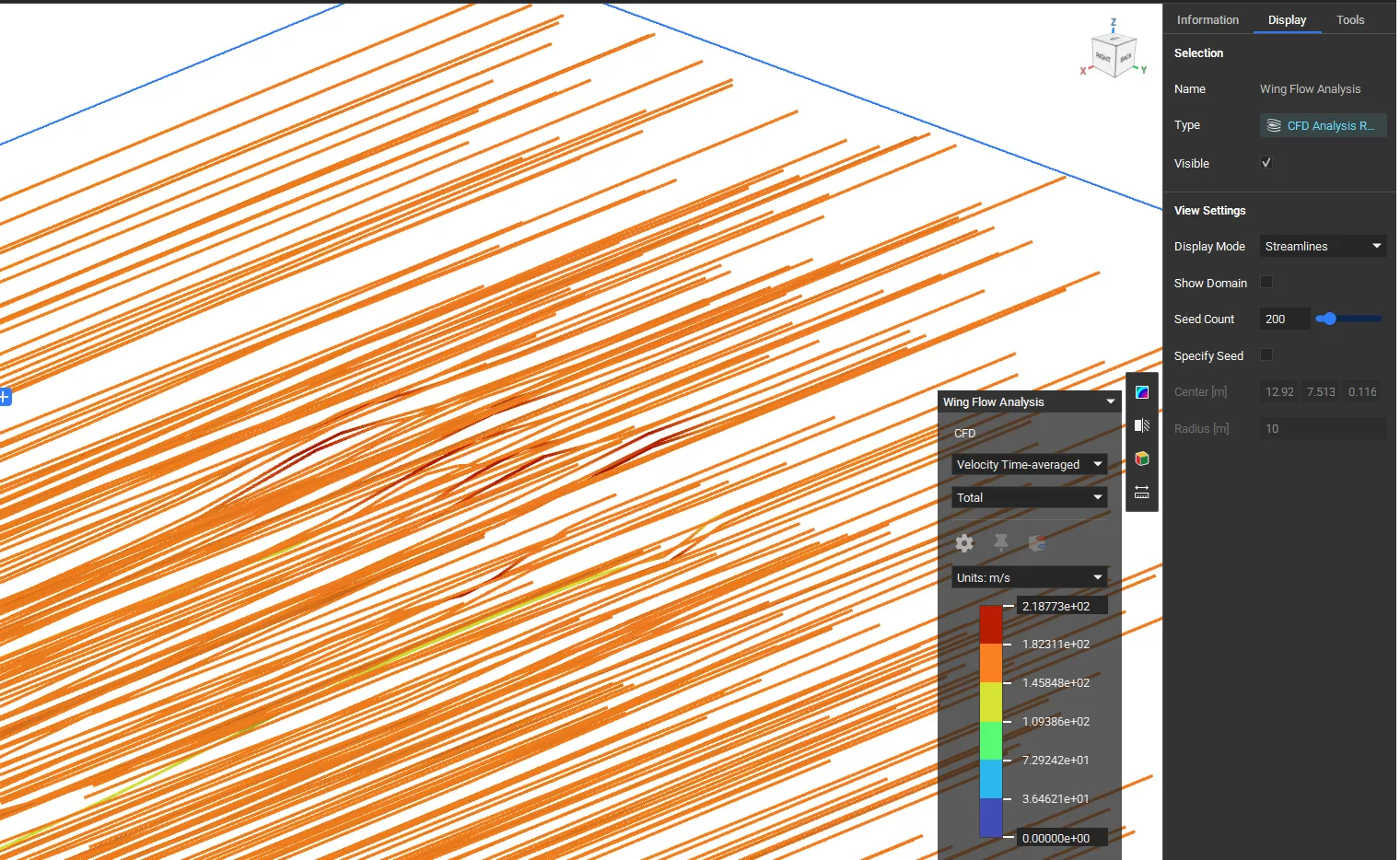
* **View Streamlines:** To visualize the flow field, select the result in the notebook and update its Display Mode to Streamlines in the View Settings.
4. **Extract Near-Body Data (Advanced Post-Processing):** To extract data points from a specific area of the fluid domain:
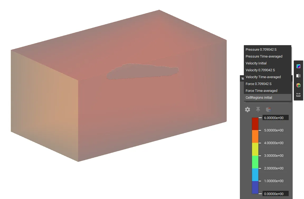
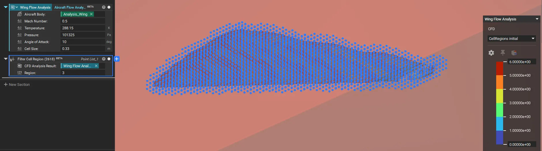
* **Find Region ID:** Select the **Aircraft Flow Analysis** block and switch the **Heads-Up Display (HUD)** to **Cell Region** to visualize and determine the identifier for the region you want to analyze (e.g., region **3** is typically the area near the aircraft body).
- **Filter Points:** Add the **Filter Cell Region** block. Input the **CFD Analysis Result** and set the **Region** ID (e.g., **3**) to generate a list of points around the aircraft body.
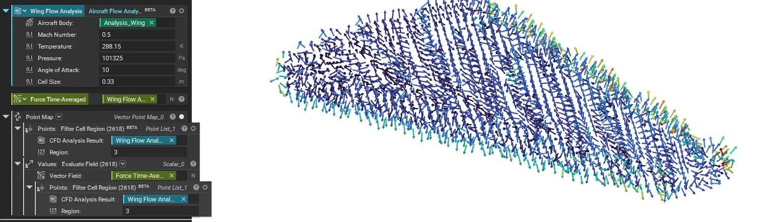
- **Evaluate Data:** Use the output **Point List** along with the **Evaluate Field** block for detailed downstream analysis of pressure or velocity near the surface.
And that's it! You've successfully run an **Aircraft Flow Analysis** to calculate the aerodynamic forces on your design.
Are you still having issues? Contact the **support team**, and we'll be happy to help!
###
### **Download the Example file:**
[Aircraft Flow Analysis Example File](https://files.learn.ntop.com/Support%20Article%20Example%20Files/Knowledge%20Base/Fluids/aircraft_flow_analysis.ntop)
## Keywords:
*analysis wing aircraft aero*