> ## Documentation Index
> Fetch the complete documentation index at: https://docs.ntop.com/llms.txt
> Use this file to discover all available pages before exploring further.
# How to variable loft?
## Question:
How do you loft an airfoil from root chord to tip chord?
## Answer:
To create a tapered loft, in this case for an airplane wing, we'll use the **Remap Field** block to scale the airfoil's profile along a path. The **Remap Field** block transforms geometry; for every point in 3D space, it provides a new coordinate location. This allows you to scale, stretch, twist, or otherwise warp a part's geometry ([How to use Remap Field to scale or translate an object](/help-articles/knowledge-base/implicit-modeling/how-to-use-remap-field-to-scale-or-translate-an-object)).
To further understand fields and remapping in nTop, look at this [Field-Driven Design White Paper by George Allen, an nTop Fellow](https://ntop.app.box.com/s/moloniur010po3gwi3v4otsyb9lr7xtg).
## Example of Scaling with a Rectangle:
Before applying this to an airfoil, let's look at a simple example: tapering a rectangle along the Y-axis.
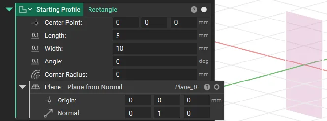
We begin with a Rectangle on the XZ plane. To create a loft, we first must define a Ramp along the Y-axis from Y=0 to Y=20mm, which applies the scaling factor for the rectangle.
We can set the **Ramp** to have an output value of *x* (the initial scale) at Y=0 and an *x/2* (200% scale) at Y=20mm.
We then use the **X Field** we created using the **Ramp** block as an input to the **Remap Field** block, which creates a tapered loft.
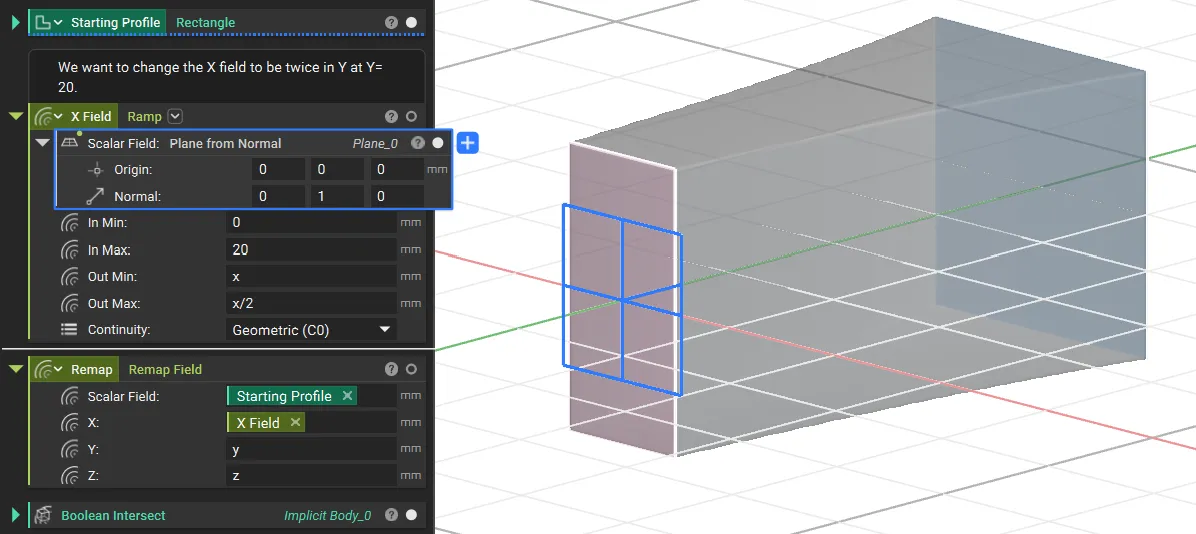**Note: The Remap Field block generates an infinite field. You must use a Boolean Intersect block to combine the remapped field with a bounding box to define your part's final geometry.**
## Applying the Concept to an Airfoil
Here's the step-by-step process for lofting an airfoil from a root profile to a smaller tip profile.
1. Set up the Airfoil Profile and Guide Curves
First, we'll import the root airfoil profile and create the guide curves that define the wing's shape.
* Import your airfoil coordinates using the **Import Points** block, and then create a 2D profile using the **Profile from Points** block.
* Use the **Rotate Object** and **Scale Object** blocks to set the final size and orientation for the airfoil. For this guide, we'll assume the profile lies on the YZ plane, centered at the origin. The Y-axis represents the chord direction, and the Z-axis represents the airfoil's height.
* Next, use the **Line by Direction** block or other line-creation methods to create the wing's **Leading Edge** and **Trailing Edge** guide curves. These curves define the wing's span, sweep, and taper.
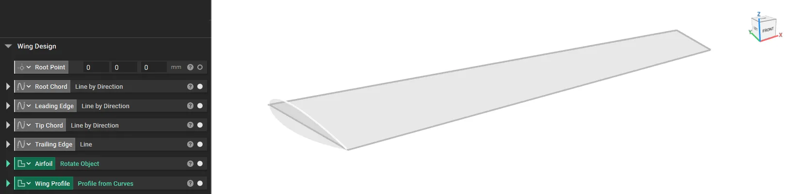At the end of this step, you will have a 2D airfoil profile and the guide curves for the wing's edges.
2. We now need to create the Y Field and the Z Field to vary the airfoil size across the wing.
### **X Field (Chord Field)**
* We must create an X field that ensures that the chord length varies from Root Chord Length to Tip Chord Length in the same taper ratio as the wing.
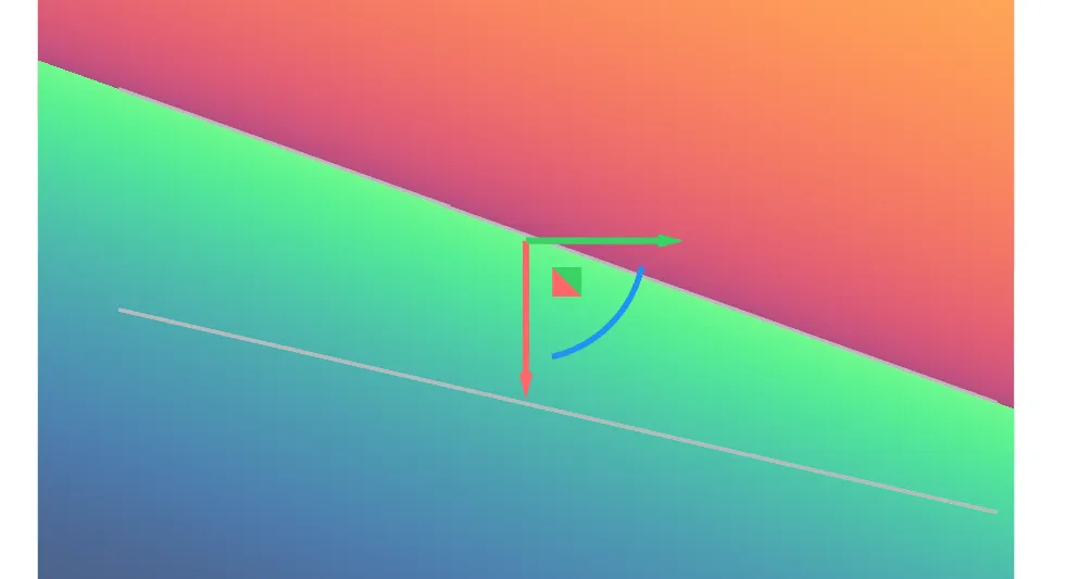
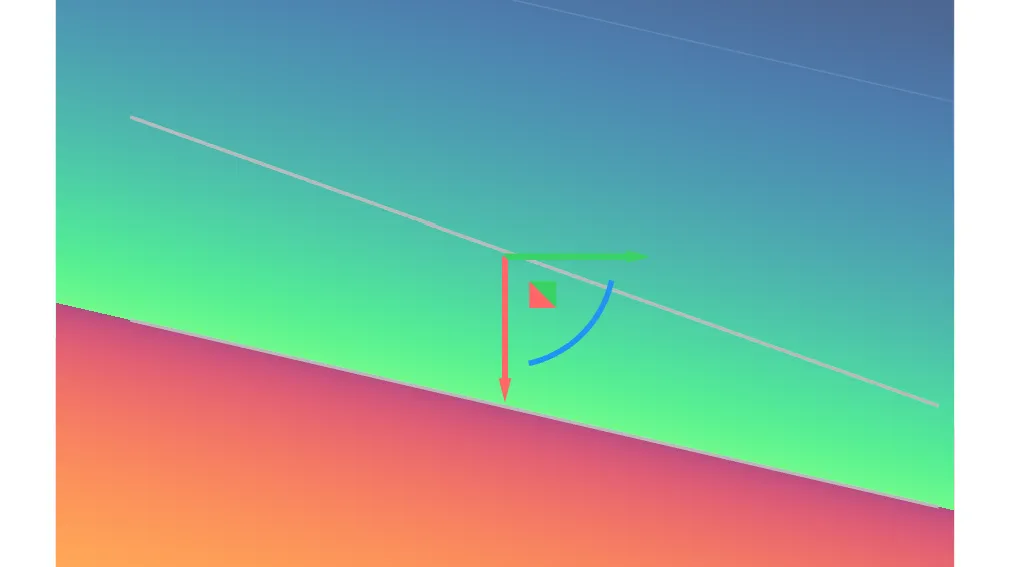
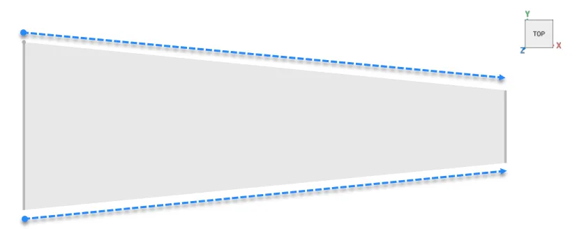 We create **Distance to LE** and **Distance to TE** using **Distance to Curve from Axis** blocks.
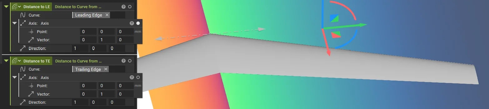***Tip: Use the Implicit view to see the distances to visualise inside (+) and outside (-)***
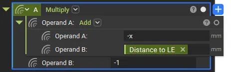
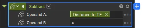
This gives us the distance, but we need the leading edge and trailing edge to follow the guide curves, so we will add *-x*, which provides us with the field that follows the guide curves. Rename these variables as **A** and **B**.
We will now use the fields created in the above step to create a Two-Body field ([The Two-Body Field](https://www.blakecourter.com/2023/07/01/two-body-field.html)) by dividing the clearance field (A-B) with the midsurface field (A+B). In our case, this results in a field whose value varies from -1 to 1 edge to edge.
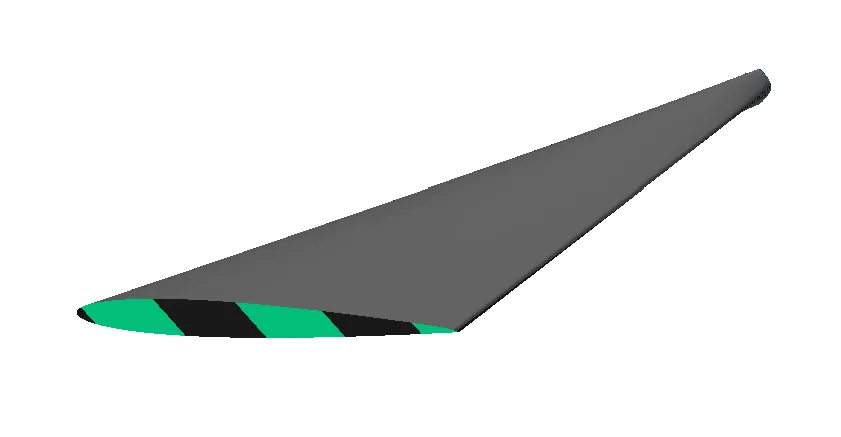
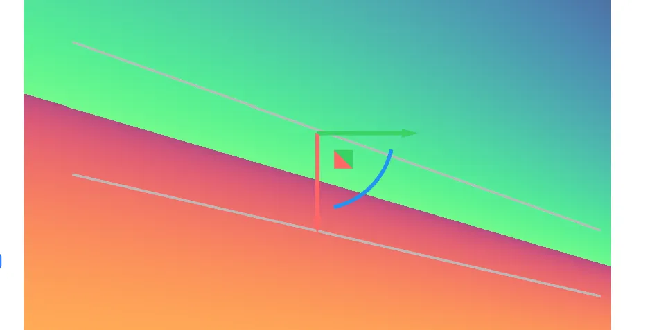Use the newly generated Y field in the **Remap Field** block. You can see the ratio is not maintained for the Z height, leading to a different profile in the end.
### **Z Field (Height Scaling Field)**
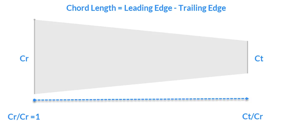
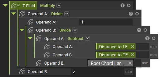
Similar to the Y field, we will generate a Z field, which will be used to remap the airfoil's Z value to maintain the ratio. We need to define a field, which is the ratio of chord length divided by root chord length, to keep the taper ratio.
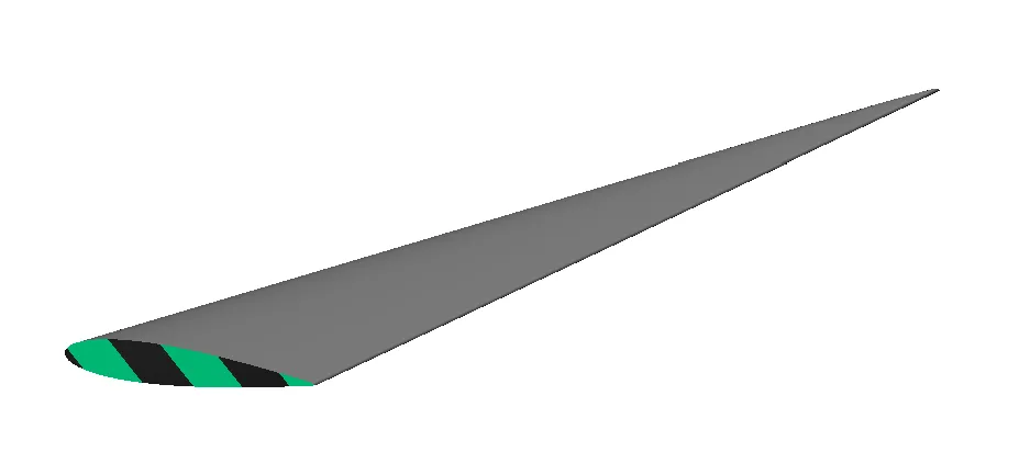
Once done, use the new Z field in the **Remap Field** block, and you should have a variable lofted wing.
We will then use **Mirror Body Symetrically** and **Boolean Intersect** blocks to trim our final wing. We highly recommend completing the [Parametric Aircraft Modeling](https://learn.ntop.com/courses/parametric-aircraft-modeling/) course to learn how to build a parametric aircraft model in nTop.
## Example File
[Example File](https://files.learn.ntop.com/Support%20Article%20Example%20Files/Knowledge%20Base/Implicit%20Modeling/variable_loft.ntop)
## Keywords:
*variable design remap loft wing airfoil two-body field airplane*