> ## Documentation Index
> Fetch the complete documentation index at: https://docs.ntop.com/llms.txt
> Use this file to discover all available pages before exploring further.
# How to offset TPMS walls
## Objective:
I am designing a heat exchanger and need to offset the TPMS walls using two different offset values.
I need to model a TPMS defined by multiple iso-contour level set inequalities.
*Note: If you are offsetting equally in both directions, you can use either the **TPMS Unit Cell with Offset** or the **Walled TPMS Unit Cell with Offset** blocks*\*.\*\*\*
## Applies to:
* TPMS
* Heat Exchangers
* Lattices
## Procedure:
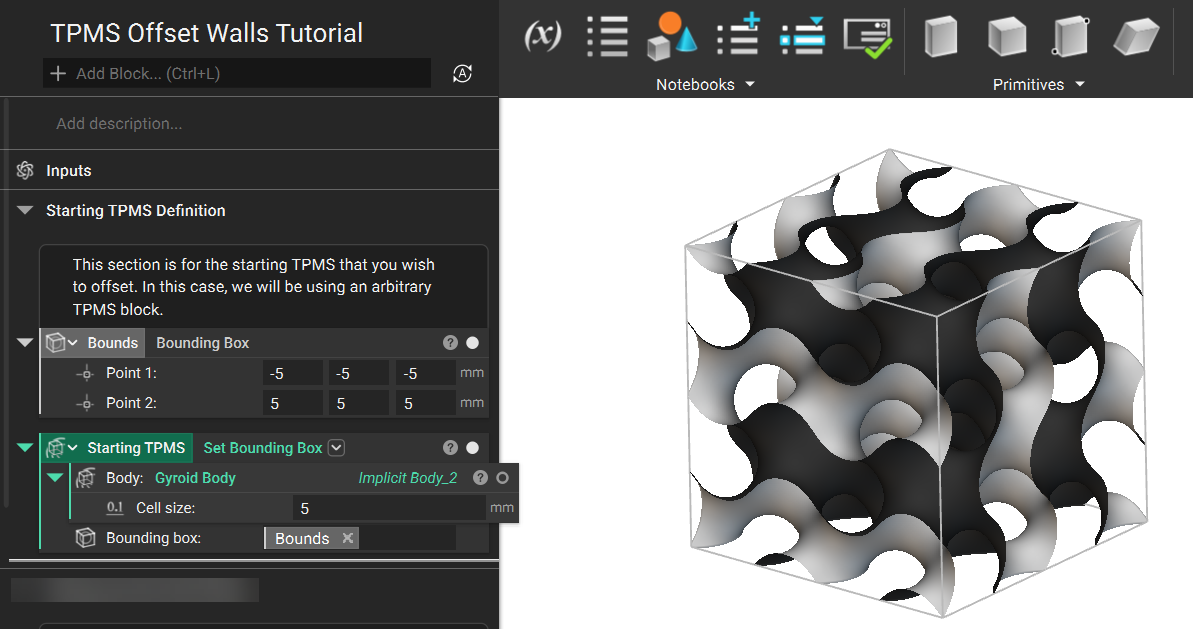
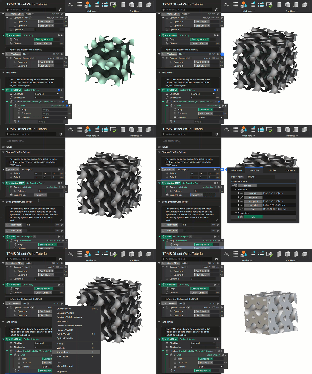
1. For this example, we will use a cube cutout of TPMS composed of a **Gyroid Body**and a **Set Bounding Box**block.
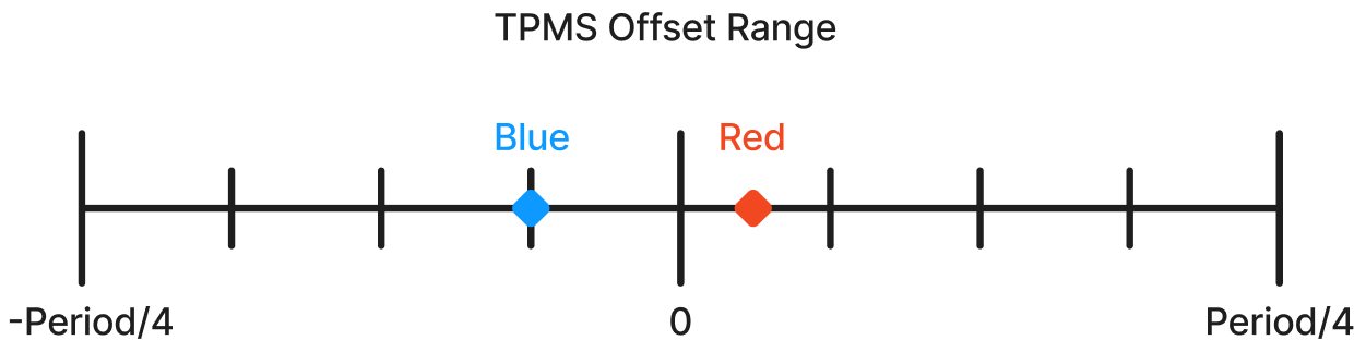
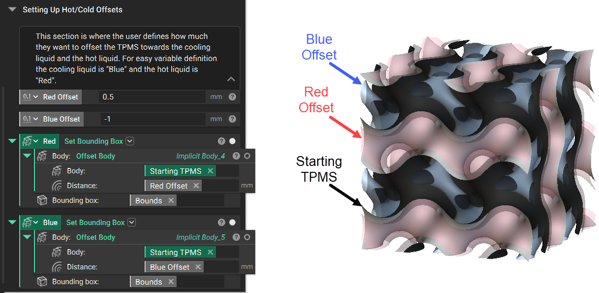
2. Next is to define the required offsets for the TPMS walls by inputting your values. Offset bodies are then created for each side using the **Offset Body**block. For this example, we will refer to the offset sides as 'Red' and 'Blue.' To help illustrate and define each of these, we altered the color and transparency of the offset bodies.
*Note: It is not mandatory to create the offset bodies; they are used to visualize the objective result.*
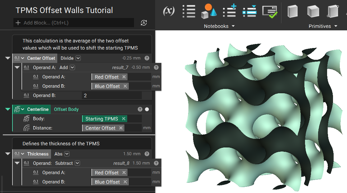
3. Using an **Add**and **Divide** block, we can calculate the average of the two offsets. This 'Center Offset' value is then used to offset the 'Starting TPMS' body. The TPMS center has now shifted into its correct position. Our last calculation uses a **Subtract**and an **Abs**block to calculate the TPMS thickness.
4. The final steps are to use a **Shell**block with the new 'Centerline' TPMS body, the calculated 'Thickness,' and the *Direction*set to Center. When this **Shell** result is used to **Boolean Intersect** with the solid body conversion of the **Bounding Box**, the result is your 'Final TPMS.'
Are you still having issues? Contact the [support team](https://support.ntopology.com/hc/en-us/requests/new), and we'll be happy to help!
## Download the Example file:
* [Example File](https://files.learn.ntop.com/Support%20Article%20Example%20Files/Knowledge%20Base/Lattices/TPMS_Offset_Walls_Example.ntop)
## Keywords:
*tpms gyroid offset question heat exchanger value wall walls*