> ## Documentation Index
> Fetch the complete documentation index at: https://docs.ntop.com/llms.txt
> Use this file to discover all available pages before exploring further.
# How to run a buckling analysis
## Objective:
Learn how to perform a Buckling Analysis.
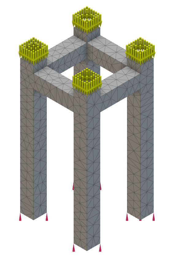
This article uses Simulation/Optimization and both of them in nTop have two requirements: FE Mesh and Boundary Conditions (BCs). Follow the instructions in the links below to prepare your model for simulation.
**FE Mesh**
* [How to create an FE Volume Mesh](/help-articles/knowledge-base/meshing-workflows/how-to-create-an-fe-volume-mesh)
* [How to create a Simulation Model](/help-articles/knowledge-base/structures/how-to-create-a-simulation-model)
**Boundary Conditions (BCs)**
* [How to select boundaries of an FE Mesh - FE Boundary by Flood Fill](/help-articles/knowledge-base/structures/how-to-select-boundaries-of-an-fe-mesh-fe-boundary-by-flood-fill)
* [How to choose boundaries of an FE Mesh - FE Boundary by Body](/help-articles/knowledge-base/structures/how-to-select-boundaries-using-boundary-by-body)
* [How to use Boundary Conditions](/help-articles/knowledge-base/structures/how-to-use-boundary-conditions)
* [How to use a CAD Face in a boundary condition](https://support.ntopology.com/hc/en-us/articles/4609628488083)
**1. Run a Buckling Analysis**
* * Add a **Buckling Analysis** block
* Insert the [Simulation Model](/help-articles/knowledge-base/structures/how-to-create-a-simulation-model) into the Model input
* Add the [Force BC](https://support.ntopology.com/hc/en-us/articles/360055857533) to the BC List input
* Press the '**+**' in the BC List to add another input
* Insert the [Restraint BC](https://support.ntopology.com/hc/en-us/articles/360055857533) into the new input slot
*Boundary conditions must contain a displacement restraint for at least one node. Otherwise, the model isn't fixed in space.*
* * Enter the Maximum Number of modes you wish to calculate.
* You can bound the Min and Max Eigenvalues, but it will return an error if there are no eigenvalues in that range.
**Note:** This is a ***linear buckling analysis***. All inertial and damping forces are neglected. To get the most accurate results, it is recommended that a *Quadratic* geometric order FE mesh be used with any analysis.
* The loads are assumed to be applied slowly until the model reaches a state of equilibrium (static assumption), and the relationship between loads and displacements is assumed to be linear.
**2. Reading the Results**
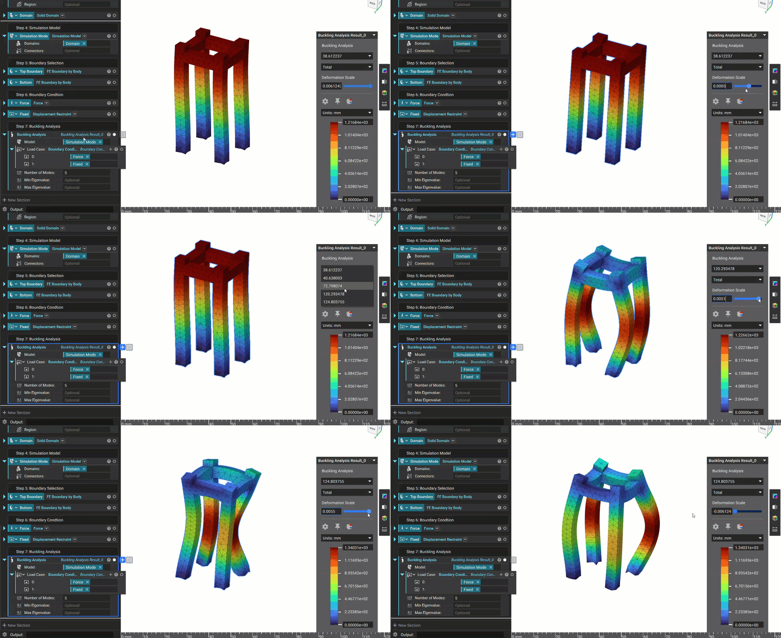
Once you run an analysis, a Heads Up Display (HUD) will appear, showing the results. The HUD allows you to toggle through Total displacement and Displacement across the X, Y, and Z axes.
* The result of the buckling simulation ('buckling load factor" property in the block's properties) is a list of factors by which the model's load(s) must be multiplied to reach the critical buckling load for each mode.
* The results are ranked by the intensity of each mode, from high to low.
And that's it! You've successfully run a buckling analysis.
Are you still having issues? Contact the [support team](https://support.ntopology.com/hc/en-us/requests/new), and we'll be happy to help!
## Download the Example file:
* [Example file](https://files.learn.ntop.com/Support%20Article%20Example%20Files/Knowledge%20Base/Simulation/Buckling%20Analysis%20Example.ntop)
## Keywords:
*analysis fea design displacement buckling value how-to eigen*