> ## Documentation Index
> Fetch the complete documentation index at: https://docs.ntop.com/llms.txt
> Use this file to discover all available pages before exploring further.
# How to use point mass
## Objective:
Learn how to use point mass
## Applies To:
* Static Analysis
* Topology Optimization
## Procedure:
This article uses Simulation/Optimization and both of them in nTop have two requirements: FE Mesh and Boundary Conditions (BCs). Follow the instructions in the links below to prepare your model for simulation.
**FE Mesh**
* [How to create an FE Volume Mesh](/help-articles/knowledge-base/meshing-workflows/how-to-create-an-fe-volume-mesh)
* [How to create a Simulation Model](/help-articles/knowledge-base/structures/how-to-create-a-simulation-model)
**Boundary Conditions (BCs)**
* [How to select boundaries of an FE Mesh - FE Boundary by Flood Fill](/help-articles/knowledge-base/structures/how-to-select-boundaries-of-an-fe-mesh-fe-boundary-by-flood-fill)
* [How to choose boundaries of an FE Mesh - FE Boundary by Body](/help-articles/knowledge-base/structures/how-to-select-boundaries-using-boundary-by-body)
* [How to use Boundary Conditions](/help-articles/knowledge-base/structures/how-to-use-boundary-conditions)
* [How to use a CAD Face in a boundary condition](https://support.ntopology.com/hc/en-us/articles/4609628488083)
Before starting, I recommend reading the simulation and optimization setup articles mentioned above.
**Preparing the Simulation Model**
We will need two Solid Domains to perform the simulation.
i) Solid Domain 1- The solid domain of the setup that has an **FE Volume Mesh** and a**Solid Attribute** ([How to create an FE Volume Mesh](/help-articles/knowledge-base/meshing-workflows/how-to-create-an-fe-volume-mesh))
ii) Solid Domain 2 - Point Mass: The solid domain of the point being referenced.
* *Point:* FE Point to create a domain from.
* *Attribute:* **Point Attribute** to define the remote mass parameters.
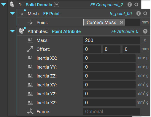
The block has the following inputs :
* *Mass:* This assigns a mass to the remote point
* *Offset*: The offset is used to specify the center of rotation for the inertia calculations. By default, the center of rotation is at the point defined in the FE Component block. This location will be moved from the point by the offset distance specified in this input. This input follows the Frame definition in the block, which is the global coordinate system by default.
* *Inertia ij*: This defines the six components of the mass moments of inertia tensor
* *Frame*: The frame is used to define the offset directions as well as the axes used to calculate the mass moment of inertia components
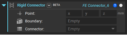
We will need a connector as we have two domains. You can use the **Rigid Connector** block to connect our two components. You'll be able to learn more about the inputs from this article ([Methods for connecting multiple FE meshes in an FE model](/help-articles/knowledge-base/structures/methods-for-connecting-multiple-fe-meshes-in-an-simulation-model)).
### Example
**Modal Analysis and Optimization of a Camera Bracket**
[Camera Bracket Example.ntop](https://files.learn.ntop.com/Support%20Article%20Example%20Files/Knowledge%20Base/Simulation/Point%20Mass%20Example.ntop)
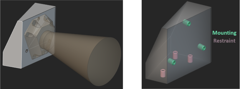
Here is a bracket (gray) that is used to connect a camera (yellow) to a mount (not pictured in the image). The requirement for this bracket is to have a first natural frequency that is greater than 350 Hz. To estimate the first natural frequency and to optimize the bracket to obey this requirement, it is essential to include the mass of the camera in the analysis. This can be defined as a remote point mass attached to the mounting locations with flexible (RBE3) connectors.
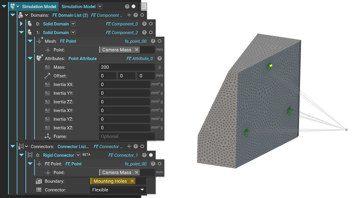
The remote point mass can be defined and attached to the mounting locations in the following way :
1. Add a second **Solid Domain** to the **Simulation Model**.
2. In the **Point** input, specify the x, y, and z location of the camera's center of mass. In the attached example, this point is specified as a variable that contains the camera's center of mass property.
3. To the Attributes input, add a**Point Attribute** and input the mass properties of the camera. In the attached example, a mass of 200 g was specified in this block.
4. In the Connectors input of the **Simulation Model**, add the **Rigid Connector** block.
5. Enter the coordinates of the point representing the camera's center of mass. Here, the center of mass variable was used to specify this input, just like the **Solid Domain** block.
6. Define the Boundary that the remote mass is connected to.
7. Finally, specify the connector type. In this example, the *Flexible* (RBE3) connector was used.
This **Simulation Model** with the remote point mass was used in Topology Optimization to define the natural frequency response ([How to use Natural Frequency Response](/help-articles/knowledge-base/optimization/how-to-use-natural-frequency-response)).
In this example, Design 2's response was defined to keep the first natural frequency above 350 Hz and a volume fraction of 0.5. Design 3's response was defined to keep the first natural frequency of the bracket-remote mass model above 350 Hz and below 1050 Hz. In addition to this, a volume fraction constraint of 0.35 was imposed on the design space.
Both designs were optimized with a compliance minimization objective for a 120g load in the +Y direction on the bracket and the camera.
| | Design 1 | Design 2 | Design 3 |
| | 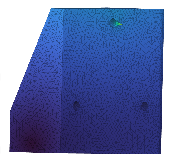 | 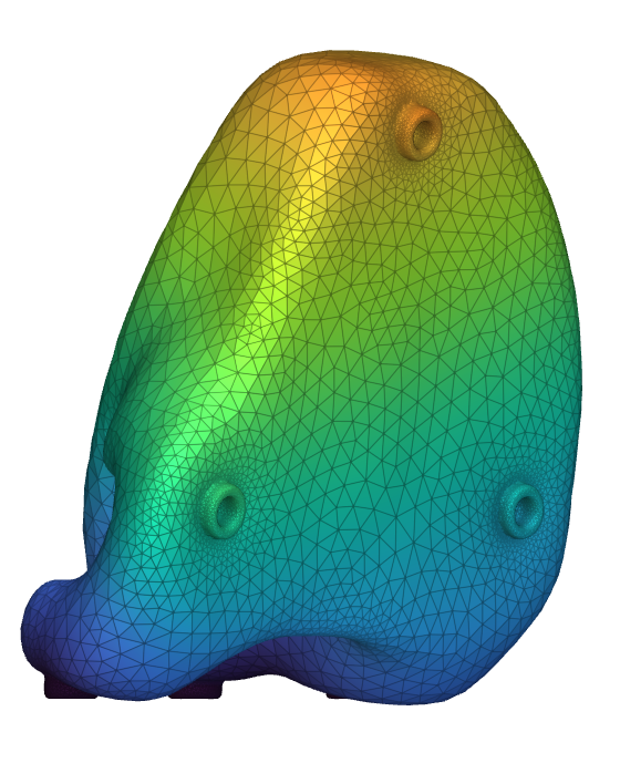 | 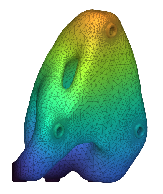 |
| Mass | 480 g | 248 g | 178 g |
| First Natural Frequency | 922 Hz | 636 Hz | 635 Hz |
The optimized bracket is ***64%*** lighter than the original design, with the first natural frequency over ***350 Hz***.
## Keywords:
*simulation fe model point mass*