> ## Documentation Index
> Fetch the complete documentation index at: https://docs.ntop.com/llms.txt
> Use this file to discover all available pages before exploring further.
# Design Responses
When setting up field optimization, use any of nTop's available design responses to specify optimization objectives and constraints. See descriptions of these responses (review of [340: Topology Optimization](/courses/340-topology-optimization/) below.
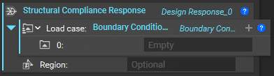
The **Structural Compliance Response**block allows users to control the stiffness of a region or part. Compliance, as the inverse of stiffness, can be minimized to provide parts with maximal stiffness or used as a constraint to control the degree of stiffness.
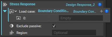
 The **Stress Response** block evaluates the maximum centroidal von Mises stress in an FE boundary at every step of your optimization. It lists a set of boundary conditions as part of a static analysis.
Including this response in a Field Optimization problem yields a longer solution time, as a full-body static structural simulation is conducted at each iteration to determine the stresses imposed upon the part.
The **Stress Response** block evaluates the maximum centroidal von Mises stress in an FE boundary at every step of your optimization. It lists a set of boundary conditions as part of a static analysis.
Including this response in a Field Optimization problem yields a longer solution time, as a full-body static structural simulation is conducted at each iteration to determine the stresses imposed upon the part.
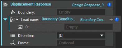
 The **Displacement Response** lists a set of boundary conditions. As a constraint, this response defines the maximum displacement of a node within a mesh of an FE boundary for a given direction. As a response, this block can maximize or minimize displacement as an objective function.
This response yields a longer solution time, as a full-body static structural simulation is conducted at each iteration to determine individual node displacements.
The **Displacement Response** lists a set of boundary conditions. As a constraint, this response defines the maximum displacement of a node within a mesh of an FE boundary for a given direction. As a response, this block can maximize or minimize displacement as an objective function.
This response yields a longer solution time, as a full-body static structural simulation is conducted at each iteration to determine individual node displacements.
 The **Volume Fraction Response** reflects the optimized geometry volume divided by the initial design space volume. You can use this block as either an objective or a constraint. Consider using it as a constraint if you know your desired mass.
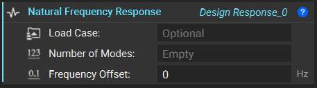
 Use the **Natural Frequency Response** to measure the smallest natural frequency of the FE Model for a set of boundary conditions. The response is computed by
*f = mini+1..N(|fi-f0|)*
where fi represents the N smallest natural frequencies obtained by solving a linear modal finite element analysis, and f0 is an offset value.
Use the **Natural Frequency Response** to measure the smallest natural frequency of the FE Model for a set of boundary conditions. The response is computed by
*f = mini+1..N(|fi-f0|)*
where fi represents the N smallest natural frequencies obtained by solving a linear modal finite element analysis, and f0 is an offset value.
 Use the**Mass Response** to measure the total mass in a region. The response is computed by integrating the density field over the region.
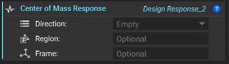
 Use the **Center of Mass Response** to measure a component of the COM vector in a region.
The response computes the response for each vector component by integrating one of the following functions over the region, where x, y, and z are the coordinates of the material point in the given reference frame, ρ is the density field, and M is the total mass in the region.
| *vx= ρ\*x/M* | *vy= ρ\*y/M* | *vz= ρ\*z/M* |
| ------------ | ------------ | ------------ |
Use the **Center of Mass Response** to measure a component of the COM vector in a region.
The response computes the response for each vector component by integrating one of the following functions over the region, where x, y, and z are the coordinates of the material point in the given reference frame, ρ is the density field, and M is the total mass in the region.
| *vx= ρ\*x/M* | *vy= ρ\*y/M* | *vz= ρ\*z/M* |
| ------------ | ------------ | ------------ |
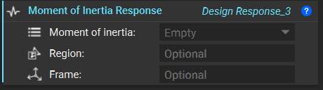
 Use a **Moment of Inertia Response** that measures a component of the mass moment of inertia tensor in some region.
For each tensor component, the response is computed by integrating one of the following functions over the region, where x, y, and z are the coordinates of the material point in the given reference frame, and ρ is the density field.
| *Ixx = ρ(y2+z2)* | *Ixy = Iyx = -ρ\*x\*y* |
| ----------------- | ---------------------- |
| *Iyy= ρ(x2 + z2)* | *Ixz = lzx = -ρ\*x\*z* |
| *lzz= ρ(x2+y2)* | *lyz = lzy = -ρ\*y\*z* |
Use a **Moment of Inertia Response** that measures a component of the mass moment of inertia tensor in some region.
For each tensor component, the response is computed by integrating one of the following functions over the region, where x, y, and z are the coordinates of the material point in the given reference frame, and ρ is the density field.
| *Ixx = ρ(y2+z2)* | *Ixy = Iyx = -ρ\*x\*y* |
| ----------------- | ---------------------- |
| *Iyy= ρ(x2 + z2)* | *Ixz = lzx = -ρ\*x\*z* |
| *lzz= ρ(x2+y2)* | *lyz = lzy = -ρ\*y\*z* |
 **Note**: Setting loaded regions to be passive can ensure a more optimal solution by preserving geometry at these places.