> ## Documentation Index
> Fetch the complete documentation index at: https://docs.ntop.com/llms.txt
> Use this file to discover all available pages before exploring further.
# Parametric FE Domains
Choose from four available Parametric FE Domain blocks to set up your model's domain(s).
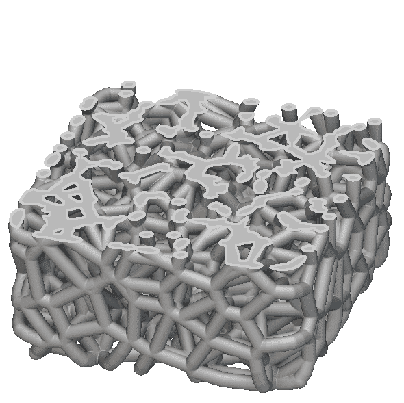 **Parametric Lattice Domain**
**Parametric Shell Domain**
**Parametric Shell-Infill Domain**
**Parametric Voronoi Domain**
Regardless of the intended output geometry, the *Mesh* input for any Parametric FE Domain will always be an **FE Volume Mesh**. Navigate the accordion below to understand each parametric domain's design parameters and input considerations.
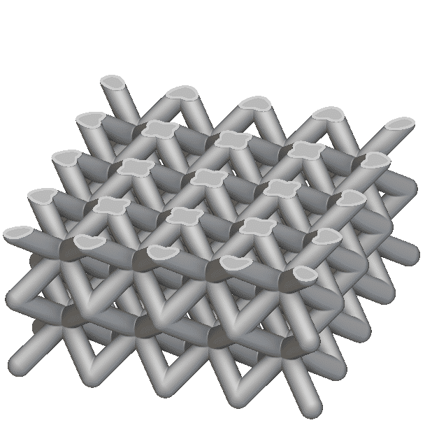
Use this domain to generate optimized lattice structures. The domain's homogenization data is gathered from thousands of simulations to correlate the beam thickness of the selected unit cell to its mechanical response. The domain supports our face-based, graph-based, or TPMS unit cells and produces a rectangular lattice structure. See the Mesh input below.
\*\*Constant Design Parameters:\*\**Unit Cell, Boundary Behavior, Cell Size*
\*\*Optimizable Design Parameters:\*\**Min/Max Thickness*
**Tips:**
* The infill material model is homogenization-based, so the model accuracy will improve as you reduce the size of your *Cell Size*/design space ratio.
* Adjust the *Initial Thickness* to view the geometry generated for the Upper/Lower bounds to ensure manufacturability before running a Field Optimization.
* Use the*Density Threshold* to alter the lattice thickness and design space. The threshold value will remove less significant design space volume. A value of 0 will remove no design space and behave solely as a thickness optimization. A value of 0.3 will remove areas with less than a 30% relative density.
* The maximum allowable lattice thickness is 1.5 times the *Cell Size*. Thickness is limited due to the data collected, as most lattices reach solid volume before this threshold.
**Parametric Lattice Domain**
**Parametric Shell Domain**
**Parametric Shell-Infill Domain**
**Parametric Voronoi Domain**
Regardless of the intended output geometry, the *Mesh* input for any Parametric FE Domain will always be an **FE Volume Mesh**. Navigate the accordion below to understand each parametric domain's design parameters and input considerations.
Use this domain to generate optimized lattice structures. The domain's homogenization data is gathered from thousands of simulations to correlate the beam thickness of the selected unit cell to its mechanical response. The domain supports our face-based, graph-based, or TPMS unit cells and produces a rectangular lattice structure. See the Mesh input below.
\*\*Constant Design Parameters:\*\**Unit Cell, Boundary Behavior, Cell Size*
\*\*Optimizable Design Parameters:\*\**Min/Max Thickness*
**Tips:**
* The infill material model is homogenization-based, so the model accuracy will improve as you reduce the size of your *Cell Size*/design space ratio.
* Adjust the *Initial Thickness* to view the geometry generated for the Upper/Lower bounds to ensure manufacturability before running a Field Optimization.
* Use the*Density Threshold* to alter the lattice thickness and design space. The threshold value will remove less significant design space volume. A value of 0 will remove no design space and behave solely as a thickness optimization. A value of 0.3 will remove areas with less than a 30% relative density.
* The maximum allowable lattice thickness is 1.5 times the *Cell Size*. Thickness is limited due to the data collected, as most lattices reach solid volume before this threshold.
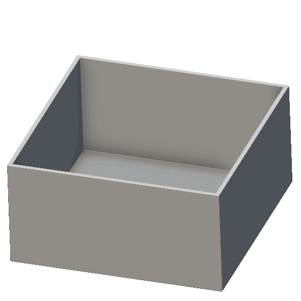
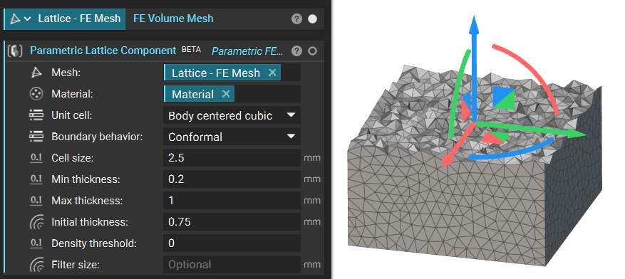 Use this domain to generate optimized shell structures.
\*\*Constant Design Parameters:\*\*N/A
\*\*Optimizable Design Parameters:\*\**Min/Max Shell Thickness*
**Tips:**
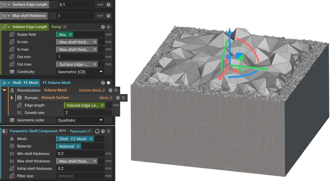
* For the most accurate results, the input mesh should be very fine from the surface through the maximum shell thickness. To ensure fine mesh elements throughout the shell region while optimizing for computation time, you can use a **Ramp** block for *Edge Length* during the **Remesh Surface** and **Volume Mesh** steps to refine your input*Mesh* across the expected shell region, as shown below.
* The *Filter Size* input is a length measure that controls the smoothness of the design parameter field. If not specified, the process will apply an estimate based on the model size. As *Filter Size* increases, the problem constraint increases, and the granularity of the output field decreases, yielding smoother geometry that could result in less optimal results.
Use this domain to generate optimized shell structures.
\*\*Constant Design Parameters:\*\*N/A
\*\*Optimizable Design Parameters:\*\**Min/Max Shell Thickness*
**Tips:**
* For the most accurate results, the input mesh should be very fine from the surface through the maximum shell thickness. To ensure fine mesh elements throughout the shell region while optimizing for computation time, you can use a **Ramp** block for *Edge Length* during the **Remesh Surface** and **Volume Mesh** steps to refine your input*Mesh* across the expected shell region, as shown below.
* The *Filter Size* input is a length measure that controls the smoothness of the design parameter field. If not specified, the process will apply an estimate based on the model size. As *Filter Size* increases, the problem constraint increases, and the granularity of the output field decreases, yielding smoother geometry that could result in less optimal results.
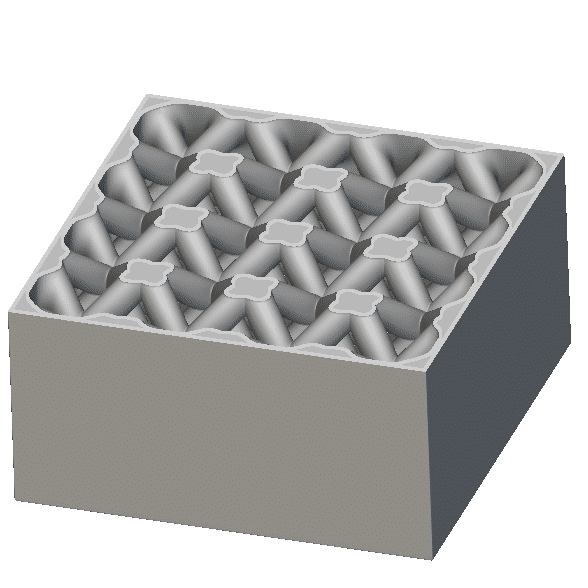
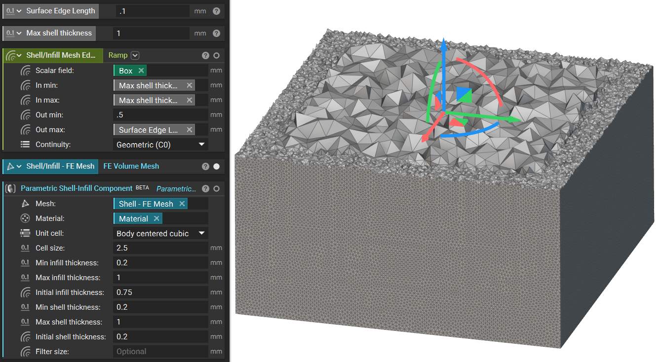
 This block utilizes the same data set used in the **Parametric Lattice Domain** to determine the homogenized properties of the lattice infill. It uses the same approach for shell optimization as the **Parametric Shell Domain** block. Therefore, you should take the same *Mesh* input considerations for this type as the two above—see the mesh below.
\*\*Constant Design Parameters:\*\**Unit Cell, Cell Size*
\*\*Optimizable Design Parameters:\*\**Min/Max Infill Thickness*, *Min/Max Shell Thickness*
**Tips:**
* The infill material model is homogenization-based, so the model accuracy will improve as you reduce the C*ell Size*/design space ratio.
This block utilizes the same data set used in the **Parametric Lattice Domain** to determine the homogenized properties of the lattice infill. It uses the same approach for shell optimization as the **Parametric Shell Domain** block. Therefore, you should take the same *Mesh* input considerations for this type as the two above—see the mesh below.
\*\*Constant Design Parameters:\*\**Unit Cell, Cell Size*
\*\*Optimizable Design Parameters:\*\**Min/Max Infill Thickness*, *Min/Max Shell Thickness*
**Tips:**
* The infill material model is homogenization-based, so the model accuracy will improve as you reduce the C*ell Size*/design space ratio.
 This block creates a Voronoi lattice domain with variable cell size and lattice thickness as the optimization parameters. Parametric Voronoi lattices use a theoretical relationship between the relative density of an open-celled foam and the resulting mechanical properties.
\*\*Constant Design Parameters:\*\*N/A
\*\*Optimizable Design Parameters:\*\**Min/Max Cell Size, Min/Max Thickness*
**Tips:**
* The *Cell Size*is the average spacing between the center points of the Voronoi lattice.
* Due to the variability of a Voronoi lattice, the result accuracy improves as relative density increases.
* If you wish to optimize only the thickness instead of the cell size, use a constant *Min*and *Max Cell Size*, and vice versa.
This block creates a Voronoi lattice domain with variable cell size and lattice thickness as the optimization parameters. Parametric Voronoi lattices use a theoretical relationship between the relative density of an open-celled foam and the resulting mechanical properties.
\*\*Constant Design Parameters:\*\*N/A
\*\*Optimizable Design Parameters:\*\**Min/Max Cell Size, Min/Max Thickness*
**Tips:**
* The *Cell Size*is the average spacing between the center points of the Voronoi lattice.
* Due to the variability of a Voronoi lattice, the result accuracy improves as relative density increases.
* If you wish to optimize only the thickness instead of the cell size, use a constant *Min*and *Max Cell Size*, and vice versa.
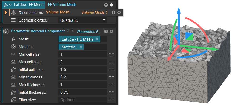 Note that the *Initial Thickness*and*Initial Cell Size*inputs are user-defined “starting places” for optimizations, specifying the initial iteration's design parameter values. The geometry generated with these design parameters will appear as the implicit view of the parametric domain.
**Note**: **To explore Custom Parametric FE Domains, see**[**this article**](https://support.ntop.com/hc/en-us/articles/16505180871315-How-to-create-Custom-Field-Optimization-Component-with-a-Custom-Graph-Unit-Cell)**.**
## Parametric FE Domain View Options
With a **Parametric FE Domain** selected, you will see view options in the bottom right corner of the viewport.
Note that the *Initial Thickness*and*Initial Cell Size*inputs are user-defined “starting places” for optimizations, specifying the initial iteration's design parameter values. The geometry generated with these design parameters will appear as the implicit view of the parametric domain.
**Note**: **To explore Custom Parametric FE Domains, see**[**this article**](https://support.ntop.com/hc/en-us/articles/16505180871315-How-to-create-Custom-Field-Optimization-Component-with-a-Custom-Graph-Unit-Cell)**.**
## Parametric FE Domain View Options
With a **Parametric FE Domain** selected, you will see view options in the bottom right corner of the viewport.
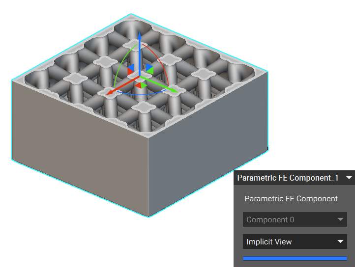
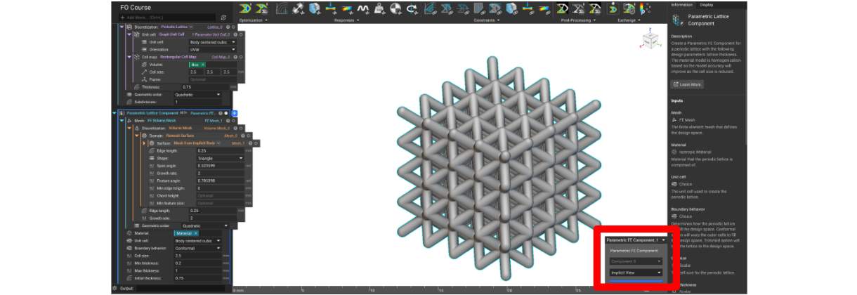 *Implicit View*allows you to view the resulting geometry by changing the *Initial values* in the input of the **Parametric FE Domain** block.
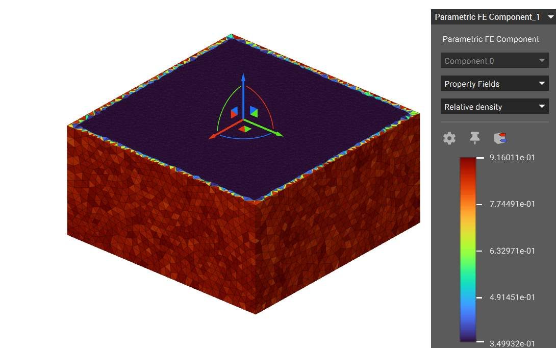
 *Property Fields*allow you to view the homogenized mechanical properties of the structure across the design space before performing field optimization. Available properties are *Relative density*, *Density*, *Young's Modulus*, *Poisson's ratio*, and *Shear modulus*.
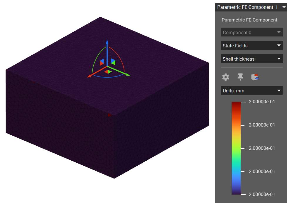
 *State Fields*allow you to view the values of the design parameters across the design space before performing the field optimization. In this case, the optimizable input is shell thickness, which is constant based on the *Initial Shell Thickness* input.