> ## Documentation Index
> Fetch the complete documentation index at: https://docs.ntop.com/llms.txt
> Use this file to discover all available pages before exploring further.
# Cell Maps
We also need a Cell Map to generate a lattice in the**Periodic Lattice** block. The Cell Map is made entirely separate from the Unit Cell. Its purpose is to define the layout of where each Unit Cell will go. To add a lattice to an implicit body, we use three types of Cell Maps: **Rectangular**, **Cylindrical**, and **Spherical**.
 The Cell Map governs where the Unit Cells will go (aligning the u, v, and w coordinates of each), allowing you to edit the size, radius, and cell counts. Each Cell Map block has a *Volume* input that uses an implicit body to define its extent and an optional *Frame* that defines the starting point and orientation of the map.
## Rectangular Cell Map
The **Rectangular Cell Map** block generates a cell map across the input volume with cells of defined *Cell Size* in rectangular coordinates. This map serves as a layout for the lattice Unit Cells.
The Cell Map governs where the Unit Cells will go (aligning the u, v, and w coordinates of each), allowing you to edit the size, radius, and cell counts. Each Cell Map block has a *Volume* input that uses an implicit body to define its extent and an optional *Frame* that defines the starting point and orientation of the map.
## Rectangular Cell Map
The **Rectangular Cell Map** block generates a cell map across the input volume with cells of defined *Cell Size* in rectangular coordinates. This map serves as a layout for the lattice Unit Cells.
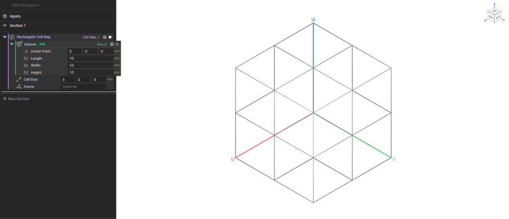 **Note**: The default Cell Map's starting point is the Minimum point of the body's bounding box. To change this starting point or the cell map's orientation, add a Frame or Plane block to the optional Frame input.
## Cylindrical Cell Map
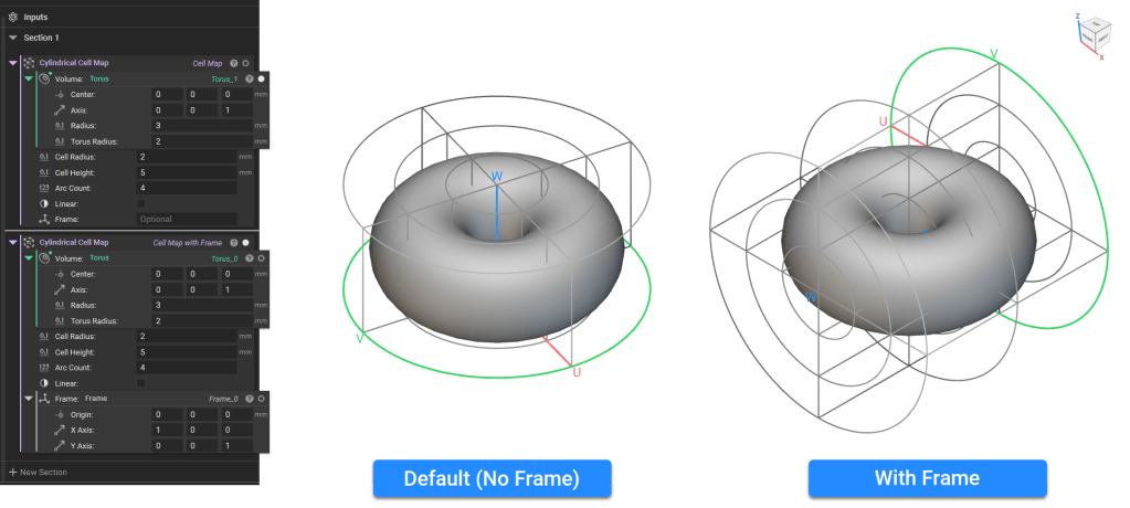
The **Cylindrical Cell Map** block generates a Cell Map with a cylindrical coordinate system that covers the entire input volume with cells using the specified *Cell radius* (U), *Cell height*(V), and *Arc count* (W).
The Cell Map edges will be default curved to the cylindrical coordinate system. Check the *Linear*input to generate straight edges only.
**Note**: The default Cell Map's starting point is the Minimum point of the body's bounding box. To change this starting point or the cell map's orientation, add a Frame or Plane block to the optional Frame input.
## Cylindrical Cell Map
The **Cylindrical Cell Map** block generates a Cell Map with a cylindrical coordinate system that covers the entire input volume with cells using the specified *Cell radius* (U), *Cell height*(V), and *Arc count* (W).
The Cell Map edges will be default curved to the cylindrical coordinate system. Check the *Linear*input to generate straight edges only.
 **Tip:** As a general rule, check the linear input when using a **Graph Unit Cell** and uncheck it when using a **TPMS Unit Cell** in the periodic lattice block. However, this will vary depending on your application and design goals.
**Note**: The default Cell Map's starting point is auto-computed based on the volume's principal axes about the center of mass. To change this starting point or the cell map's orientation, add a **Frame** block to the optional Frame input.
## Spherical Cell Map
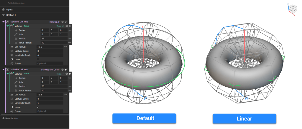
The **Spherical Cell Map** generates a Cell Map with a spherical coordinate system that spans the entire input volume with cells using the specified *Cell radius* (U), *Latitude count* (V), and *Longitude count*(W).
The Cell Map edges will be default curved to the cylindrical coordinate system. Check the *Linear*input to generate straight edges only.
**Tip:** As a general rule, check the linear input when using a **Graph Unit Cell** and uncheck it when using a **TPMS Unit Cell** in the periodic lattice block. However, this will vary depending on your application and design goals.
**Note**: The default Cell Map's starting point is auto-computed based on the volume's principal axes about the center of mass. To change this starting point or the cell map's orientation, add a **Frame** block to the optional Frame input.
## Spherical Cell Map
The **Spherical Cell Map** generates a Cell Map with a spherical coordinate system that spans the entire input volume with cells using the specified *Cell radius* (U), *Latitude count* (V), and *Longitude count*(W).
The Cell Map edges will be default curved to the cylindrical coordinate system. Check the *Linear*input to generate straight edges only.
 ### View Settings
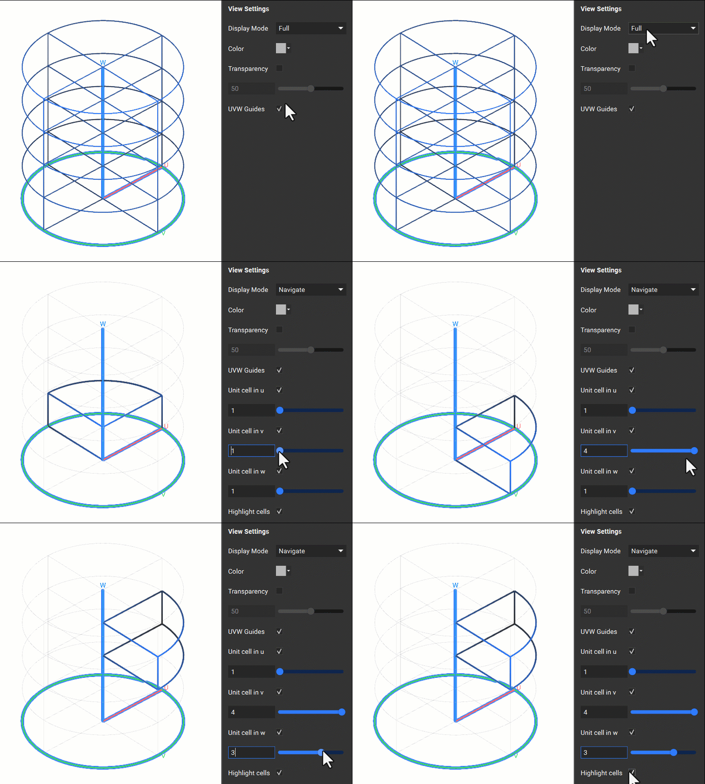
When creating the Cell Map, you can isolate the block using 'I' and view the Full Map or Navigate the Map using the heads-up display. The Navigate and Full display modes are available in the Display tab of the Right Panel. The Navigate mode allows you to view individual cells.
### View Settings
When creating the Cell Map, you can isolate the block using 'I' and view the Full Map or Navigate the Map using the heads-up display. The Navigate and Full display modes are available in the Display tab of the Right Panel. The Navigate mode allows you to view individual cells.