> ## Documentation Index
> Fetch the complete documentation index at: https://docs.ntop.com/llms.txt
> Use this file to discover all available pages before exploring further.
# FE Meshes
Creating an FE Mesh is one of the first steps in setting up a Simulation or a Topology Optimization. The image below shows the basic steps for creating an FE Mesh. If you are working with a solid body, we recommend the **FE Volume Mesh**, and for lattices, we recommend **FE Lattice Mesh**.
 ## FE Volume Mesh
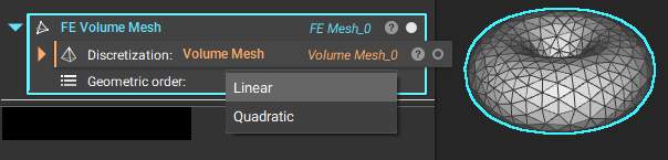
The **FE Volume Mesh** block places FE elements over volume mesh elements. The geometric order defines the number of nodal elements placed in the mesh elements.
## FE Volume Mesh
The **FE Volume Mesh** block places FE elements over volume mesh elements. The geometric order defines the number of nodal elements placed in the mesh elements.
 ## FE Surface Mesh
The **FE Surface Mesh** block creates 2D surface elements with 'isoparametric' elements. The thickness defined is normal to the surface in the Shell Attribute.
## FE Surface Mesh
The **FE Surface Mesh** block creates 2D surface elements with 'isoparametric' elements. The thickness defined is normal to the surface in the Shell Attribute.
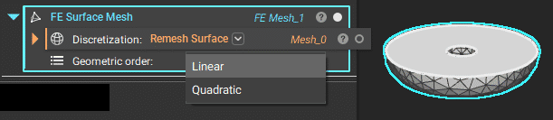 **Note**: The toolkit block **FE Shell Mesh** remeshes and creates a surface mesh using the block above.
## FE Lattice Mesh
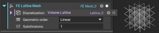
The **FE Lattice Mesh**block creates beam elements coinciding with lattice beams. The thickness of the beams is defined in FE Attributes (can be nonuniform).
**Note**: The toolkit block **FE Shell Mesh** remeshes and creates a surface mesh using the block above.
## FE Lattice Mesh
The **FE Lattice Mesh**block creates beam elements coinciding with lattice beams. The thickness of the beams is defined in FE Attributes (can be nonuniform).
 ## Merge FE Meshes
When some regions are easier to mesh than others, you can mesh them separately and join them using **Merge FE Meshes**. This process is good for interfacing surfaces.
## Merge FE Meshes
When some regions are easier to mesh than others, you can mesh them separately and join them using **Merge FE Meshes**. This process is good for interfacing surfaces.
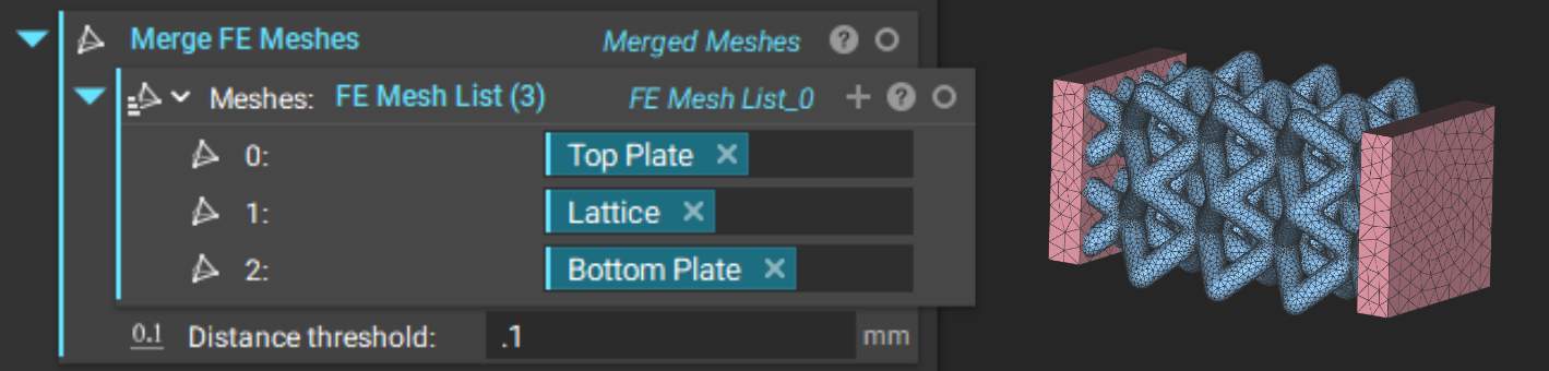 To merge, at least one node from each mesh must be within the distance threshold. Use distance threshold of at least ½ of mesh size.
**Tip:** **General rules of thumb for elements in FEA**
\*\*Thermal:\*\*at least 1 element across thin or small design features and or parts. Typically linear, unless you start to tie in deflection or stress due to thermal distribution.
\*\*Deflection:\*\*at least 3 elements across thin or small design features and or parts, and is typically linear.
\*\*Stress:\*\*at least 5 elements across thin or small design features and or parts. In nTop, use the Quadratic Geometric order (i.e., Mid-side nodes).
To merge, at least one node from each mesh must be within the distance threshold. Use distance threshold of at least ½ of mesh size.
**Tip:** **General rules of thumb for elements in FEA**
\*\*Thermal:\*\*at least 1 element across thin or small design features and or parts. Typically linear, unless you start to tie in deflection or stress due to thermal distribution.
\*\*Deflection:\*\*at least 3 elements across thin or small design features and or parts, and is typically linear.
\*\*Stress:\*\*at least 5 elements across thin or small design features and or parts. In nTop, use the Quadratic Geometric order (i.e., Mid-side nodes).