> ## Documentation Index
> Fetch the complete documentation index at: https://docs.ntop.com/llms.txt
> Use this file to discover all available pages before exploring further.
# Creating a Simulation Model
A **Simulation Model** brings together all of the necessary elements for the part to be analyzed, whether in simulation, optimization, or further analysis. It is built up of **Domains** and **Connectors**.
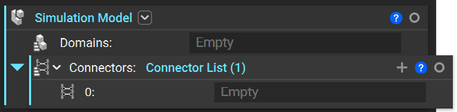 Each Domain contains an **Implicit Body**/**FE Mesh**/**Lattice** and **Attributes**, while connectors are made up of **Tie Constraints**, **Structural Bonded Contacts**, **etc.** that allow the analysis of multiple Domains. A **Simulation Model** does not need a connector if only one Domain exists. If it has multiple Domains, there will always be one less connector than the total number of Domains. Later, we will also walk through creating an Simulation Model from scratch.
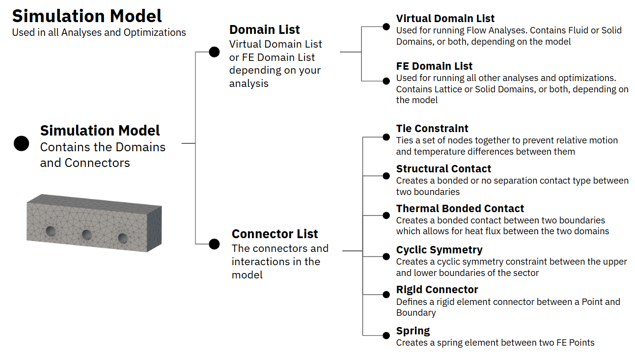
The flowchart below explains how a Simulation Model is configured:
Each Domain contains an **Implicit Body**/**FE Mesh**/**Lattice** and **Attributes**, while connectors are made up of **Tie Constraints**, **Structural Bonded Contacts**, **etc.** that allow the analysis of multiple Domains. A **Simulation Model** does not need a connector if only one Domain exists. If it has multiple Domains, there will always be one less connector than the total number of Domains. Later, we will also walk through creating an Simulation Model from scratch.
The flowchart below explains how a Simulation Model is configured: