> ## Documentation Index
> Fetch the complete documentation index at: https://docs.ntop.com/llms.txt
> Use this file to discover all available pages before exploring further.
# Displacement Restraint
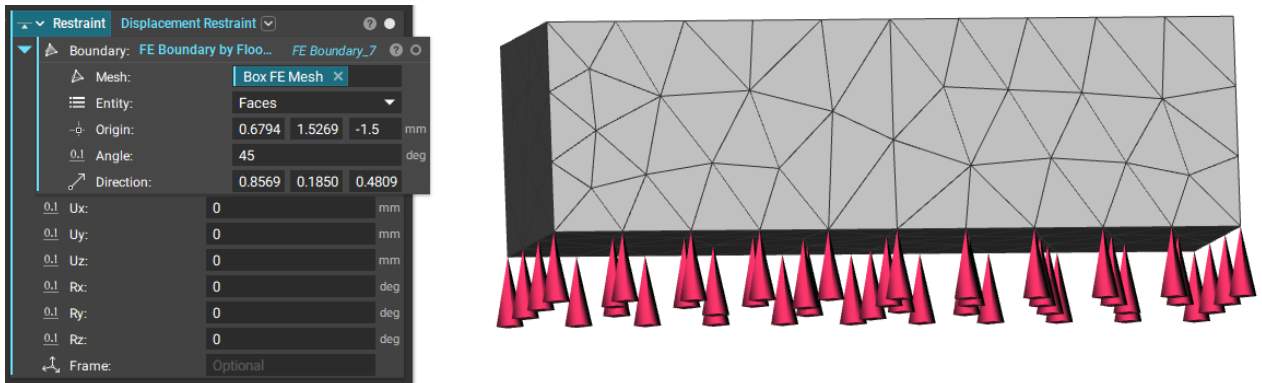
When running a static analysis, you will need a displacement restraint to fix a part in space. The **Displacement Restraint** is represented by red cones at the FE Boundary chosen. A Displacement Restraint is usually required when forces are involved to ensure the part is fixed in space. Without it, the simulation wouldn't be able to run. We have two blocks for displacement restraints: **Displacement Restraint**and**Point Restraint**.
### Displacement Restraint
A **Displacement Restraint** restrains the selected boundary entities in up to six degrees of freedom. If an input is empty, the corresponding degree of freedom will be unrestrained. We also have Beta version of this block that takes CAD faces if you are working with a CAD body.
 ### Point Restraint
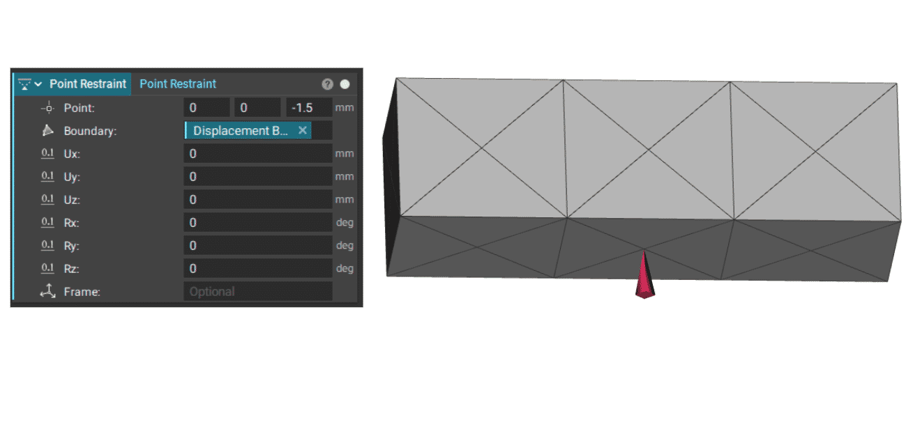
A **Point Restraint**applies a displacement restraint to a remote point attached to selected boundary entities using rigid body elements.
### Point Restraint
A **Point Restraint**applies a displacement restraint to a remote point attached to selected boundary entities using rigid body elements.