> ## Documentation Index
> Fetch the complete documentation index at: https://docs.ntop.com/llms.txt
> Use this file to discover all available pages before exploring further.
# Defining Constraints
The user must also provide constraints for the **Topology Optimization** block. An underconstrained TopOpt process will fill in or remove all volume from the design region because those results lead to the minimization or maximization of the design response. Therefore, TopOpt procedures must be properly constrained to achieve meaningful results.
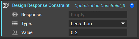
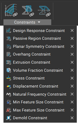 A defined design response drives the TopOpt result. The most commonly used constraint applies a minimum or maximum bound to a design response, such as compliance, volume fraction, displacement, or stress.
Choose a design response that must be restricted/constrained in the topology optimization.
You may choose any of the design responses to constrain, ensuring the solution meets and falls under or exceeds your quantitative restriction (dependent on your choice), for example:
* Limiting the final volume of your part to 30% or less (with an input of 0.3)
* Limiting the stress in a particular FE region to 30 MPa or less
* Limiting the displacement of a node in a particular FE region to 2 mm or less
**Tips:**
In cases where you want your solution to meet or exceed quantitative restrictions, you may want to include an upper and lower bound in the constraint.This tool ensures your optimization objective converges to an ideal solution. Rarely is structural compliance used as an optimization constraint, as it is often chosen as the objective.
A defined design response drives the TopOpt result. The most commonly used constraint applies a minimum or maximum bound to a design response, such as compliance, volume fraction, displacement, or stress.
Choose a design response that must be restricted/constrained in the topology optimization.
You may choose any of the design responses to constrain, ensuring the solution meets and falls under or exceeds your quantitative restriction (dependent on your choice), for example:
* Limiting the final volume of your part to 30% or less (with an input of 0.3)
* Limiting the stress in a particular FE region to 30 MPa or less
* Limiting the displacement of a node in a particular FE region to 2 mm or less
**Tips:**
In cases where you want your solution to meet or exceed quantitative restrictions, you may want to include an upper and lower bound in the constraint.This tool ensures your optimization objective converges to an ideal solution. Rarely is structural compliance used as an optimization constraint, as it is often chosen as the objective.
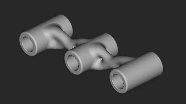
 The **Passive Regions Constraint**specifies a volume in which the topology will not be modified by the TopOpt process. The elements within a passive region (the three holes in the image below) will still be considered in the calculations throughout the TopOpt, but TopOpt density will remain 1. Specify any FE region. By default, the FE regions for the boundary conditions are passive. During post-processing with the **Smoothen Body** block, regions designated to be passive are also smoothened.
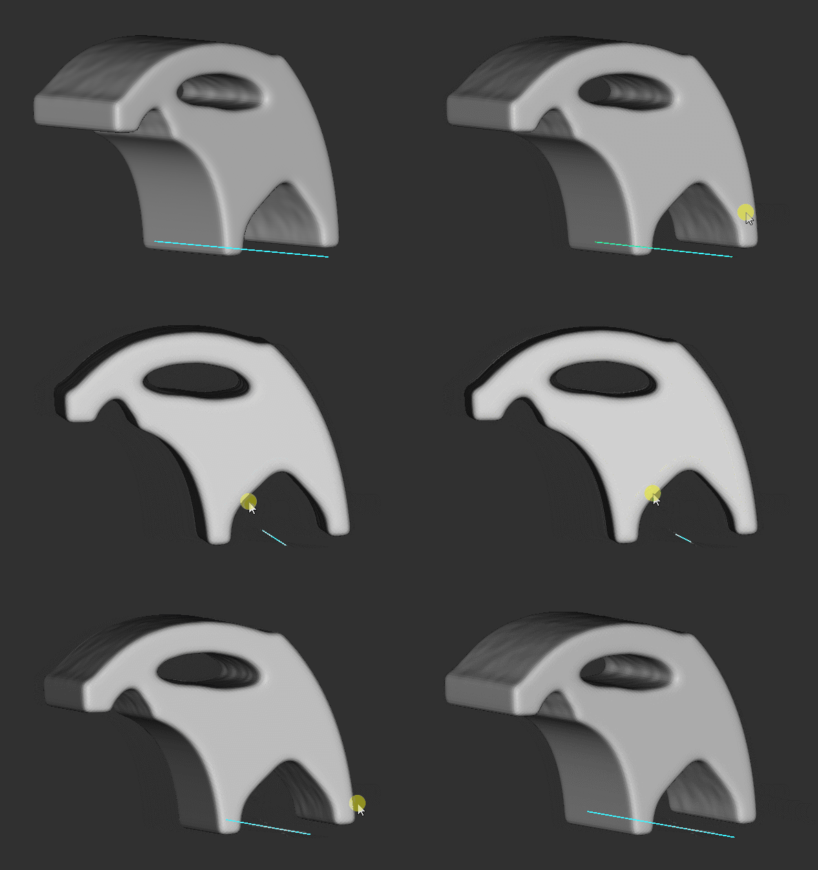
 The **Extrusion Constraint**will produce a TopOpt part with a consistent profile along the direction of a specified curve.
To accurately use this constraint, the user must create a curve (orthogonal to the full design space – starting at/before and ending at/after) through which all tet elements are fixed to a high-density threshold.
A defined extrusion profile along the direction of a specified curve creates a TopOpt result to have a consistent profile for manufacturing. To best use this block with a fully extrudable part, set the boundary penalty of your TopOpt to 0 (Neumann criteria). This will help force tet elements to follow the extrusion curve more appropriately.
The **Extrusion Constraint**will produce a TopOpt part with a consistent profile along the direction of a specified curve.
To accurately use this constraint, the user must create a curve (orthogonal to the full design space – starting at/before and ending at/after) through which all tet elements are fixed to a high-density threshold.
A defined extrusion profile along the direction of a specified curve creates a TopOpt result to have a consistent profile for manufacturing. To best use this block with a fully extrudable part, set the boundary penalty of your TopOpt to 0 (Neumann criteria). This will help force tet elements to follow the extrusion curve more appropriately.
 A **Planar Symmetry Constraint** can be added to the constraints list to ensure symmetry in the resulting TopOpt part. Using the **Mirror FE Mesh** block, it is recommended to use a symmetrical FE Mesh that matches the planar symmetry of the TopOpt constraint. Although the design space and TopOpt result will be symmetric when this constraint is used, the boundary conditions do not have to be symmetrical. A defined plane creates a symmetric TopOpt result with the same density on either side.
The model should be inherently symmetric for this to work. Planes should be orthogonal to the model and placed through the centroid of the FE model.
**Note:** A symmetric mesh about the plane splitting the part offers a more optimal solution.
To create a symmetric mesh:
* Cut the design space in half
* FE mesh this half
* Mirror the FE Mesh about your plane to create the second half of your design space.
* Merge the FE meshes to tie both halves back together
A **Planar Symmetry Constraint** can be added to the constraints list to ensure symmetry in the resulting TopOpt part. Using the **Mirror FE Mesh** block, it is recommended to use a symmetrical FE Mesh that matches the planar symmetry of the TopOpt constraint. Although the design space and TopOpt result will be symmetric when this constraint is used, the boundary conditions do not have to be symmetrical. A defined plane creates a symmetric TopOpt result with the same density on either side.
The model should be inherently symmetric for this to work. Planes should be orthogonal to the model and placed through the centroid of the FE model.
**Note:** A symmetric mesh about the plane splitting the part offers a more optimal solution.
To create a symmetric mesh:
* Cut the design space in half
* FE mesh this half
* Mirror the FE Mesh about your plane to create the second half of your design space.
* Merge the FE meshes to tie both halves back together
 An [**Overhang Constraint**](https://support.ntopology.com/hc/en-us/articles/360060738793-How-to-use-the-overhang-constraint-in-Topology-Optimization), typically used for additive manufacturability, controls the maximum overhang angle a Topology Optimization produces.
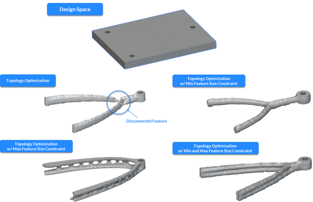
 The Min Feature Size Constraint block can be used as a constraint in the Topology Optimization block to maintain the feature sizes of the optimized design space above a user-defined value. This block is typically used to correct feature disconnections in the optimization result and to enforce a minimum feature size limit to the design space based on requirements from a manufacturing process.
 The Max Feature Size Constraint block can be used as a constraint in the Topology Optimization block to maintain the feature sizes of the optimized design space below a user-defined value. This block can be used with the Min Feature Size Constraint to enforce an upper and lower limit to the feature sizes generated from Topology Optimization.
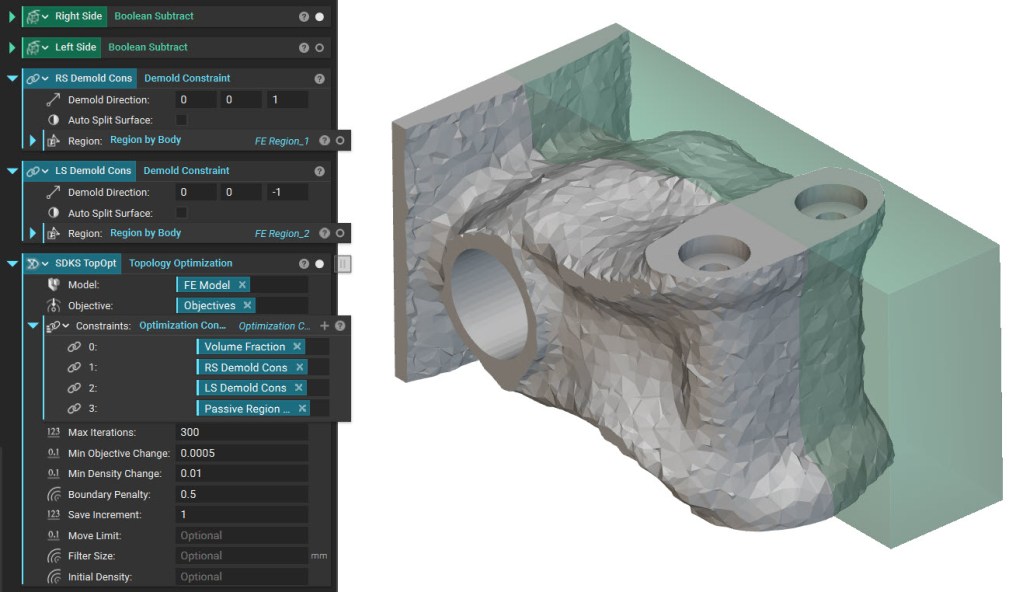
 The Demold Constraint block ensures the manufacturability of the final results for castings or plastic injection molding parts. The block prevents overhangs or undercuts based on a defined Demold Direction. You can use this block for a single draw, a split draw with a variable surface, or a split draw with a known surface.
 A Pattern Repetition Constraint ensures the TopOpt is consistent across a cell map, defining the repeated pattern.