> ## Documentation Index
> Fetch the complete documentation index at: https://docs.ntop.com/llms.txt
> Use this file to discover all available pages before exploring further.
# Method 1: Using Solid Elements
This method treats your lattice structure as solid elements by creating a volumetric finite element mesh of the entire lattice structure.
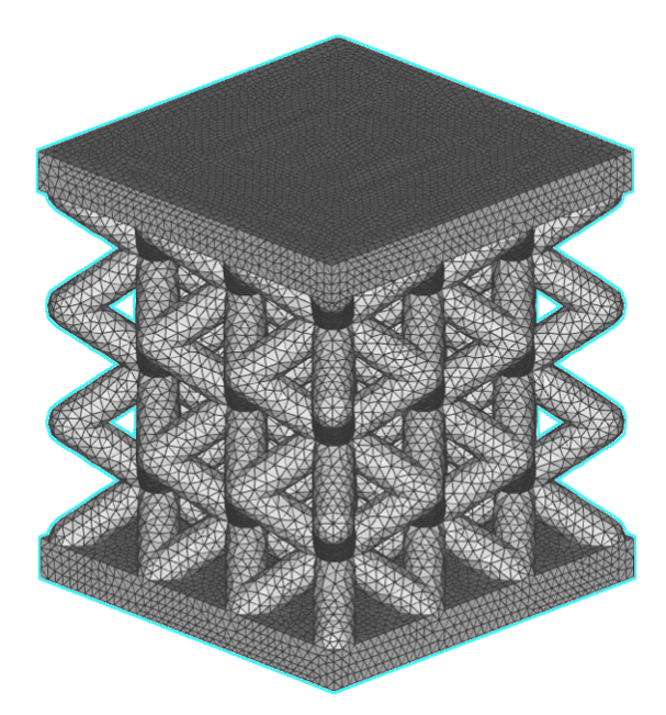 **Advantages:**
* Best accuracy
* Considers blend lattice-wall radius
* Captures edge effects and stress concentrations
**Limitations:**
* Meshing challenges for complex lattice structures
* Small mesh element size is needed to capture the detail of the lattice
* Result is dependent on mesh quality
* Takes a long time to compute
* Generates large file size
## Setup
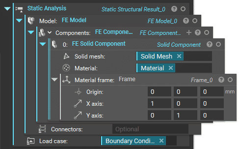
The setup for this method is the same as for running static structural analysis on any other non-latticed parts. This includes creating an **FE Model** containing the **FE Solid Component**of your lattice structure and defining your load case in the **Boundary Conditions**. You can then put the completed **FE Model** and **Boundary Conditions** into the **Static Analysis**block and let it run.
**Advantages:**
* Best accuracy
* Considers blend lattice-wall radius
* Captures edge effects and stress concentrations
**Limitations:**
* Meshing challenges for complex lattice structures
* Small mesh element size is needed to capture the detail of the lattice
* Result is dependent on mesh quality
* Takes a long time to compute
* Generates large file size
## Setup
The setup for this method is the same as for running static structural analysis on any other non-latticed parts. This includes creating an **FE Model** containing the **FE Solid Component**of your lattice structure and defining your load case in the **Boundary Conditions**. You can then put the completed **FE Model** and **Boundary Conditions** into the **Static Analysis**block and let it run.
 ## FE Solid Component
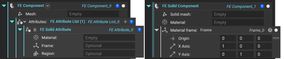
You can use either the **FE Component** block and fill out the Attribute as **FE Solid Attribute** or the built-in toolkit block **FE Solid Component,** which lets you skip the step of defining the attribute type.
## FE Solid Component
You can use either the **FE Component** block and fill out the Attribute as **FE Solid Attribute** or the built-in toolkit block **FE Solid Component,** which lets you skip the step of defining the attribute type.
 ## FE Volume Mesh for Lattices
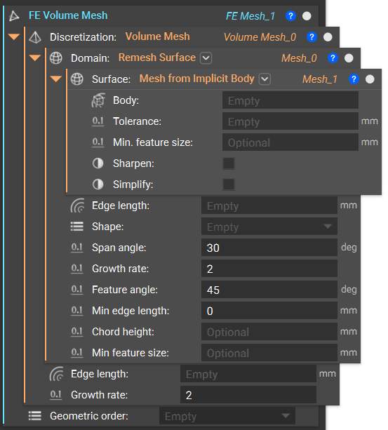
To create the**FE Volume Mesh**of your lattice structure, which you need as input for the FE Component, start with this recommended workflow. This combination of blocks converts your implicit body into a surface mesh, remeshes it to be suitable for FEA, then generates and discretizes a volumetric mesh with assigned nodes.
The recommended tolerance for the**Mesh from Implicit Body** block is 30% of the smallest feature in your part.
## FE Volume Mesh for Lattices
To create the**FE Volume Mesh**of your lattice structure, which you need as input for the FE Component, start with this recommended workflow. This combination of blocks converts your implicit body into a surface mesh, remeshes it to be suitable for FEA, then generates and discretizes a volumetric mesh with assigned nodes.
The recommended tolerance for the**Mesh from Implicit Body** block is 30% of the smallest feature in your part.
 **Tip:**
Turn on *Manual Run Mode*at the **Remesh Surface** block using the right-click menu so that you can try out different input values in the **Mesh from Implicit Body**block without having to run through the whole workflow. You can do the same for **Volume Mesh** as well. This is to ensure you have a good initial mesh with properties closed true, edge manifold true, and self-intersecting false before moving on to the next steps.
For complex geometries like lattices, we recommend using the second overload of the **Mesh from Implicit Body** block by clicking on the drop-down arrow to the right of the block name. This allows you to globally or locally sharpen your mesh, which can help to resolve areas with high element density.
For a deep dive into best practices for meshing complex designs, take a look at this video on [surface meshing techniques](https://learn.ntop.com/courses/surface-meshing-techniques/).
If**Volume Mesh**fails for your geometry, try using the **Robust Tetrahedral Mesh** block instead. It will take longer to compute but can is more robust in dealing with complex parts.
**Tip:**
Turn on *Manual Run Mode*at the **Remesh Surface** block using the right-click menu so that you can try out different input values in the **Mesh from Implicit Body**block without having to run through the whole workflow. You can do the same for **Volume Mesh** as well. This is to ensure you have a good initial mesh with properties closed true, edge manifold true, and self-intersecting false before moving on to the next steps.
For complex geometries like lattices, we recommend using the second overload of the **Mesh from Implicit Body** block by clicking on the drop-down arrow to the right of the block name. This allows you to globally or locally sharpen your mesh, which can help to resolve areas with high element density.
For a deep dive into best practices for meshing complex designs, take a look at this video on [surface meshing techniques](https://learn.ntop.com/courses/surface-meshing-techniques/).
If**Volume Mesh**fails for your geometry, try using the **Robust Tetrahedral Mesh** block instead. It will take longer to compute but can is more robust in dealing with complex parts.