> ## Documentation Index
> Fetch the complete documentation index at: https://docs.ntop.com/llms.txt
> Use this file to discover all available pages before exploring further.
# Modeling a Fuselage
export const YouTubeVideo = ({src, title, caption}) => {
return
;
};
In this lesson, we'll model a fuselage using splines and conics. Aircraft fuselage geometry can range from simple streamlined forms to highly complex shapes with intricate cross-sectional variations. We'll focus on a straightforward approach that demonstrates core modeling principles using spline curves to define the fuselage profile and conic sections to control cross-sectional shape transitions.
**Tip:**
*There are various ways to approach fuselage modeling depending on your specific requirements. For more advanced control, consider exploring detailed parameterization schemes for design variants or cubic Bézier curves for precise curvature management.*
We will create our fuselage through these steps:
1. Define **guide splines** for the top, bottom, and side profiles.
2. Establish a **central axis** and calculate **distance fields** from each spline.
3. Generate fuselage surfaces using **conic sections**.
4. Apply **bounding boxes** and **boolean operations** to create the final geometry.
You can follow along using the example file.
**Downloadable Files:**
[Fuselage.ntop](https://storage.googleapis.com/files-learn/Courses/Aircraft%20Modeling/Fuselage.ntop)
*This file was last updated in nTop 5.30.2*
## 1. Guide Splines
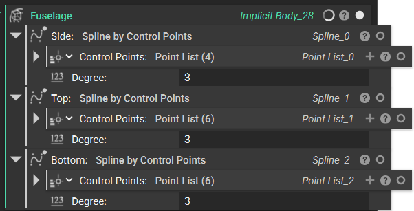
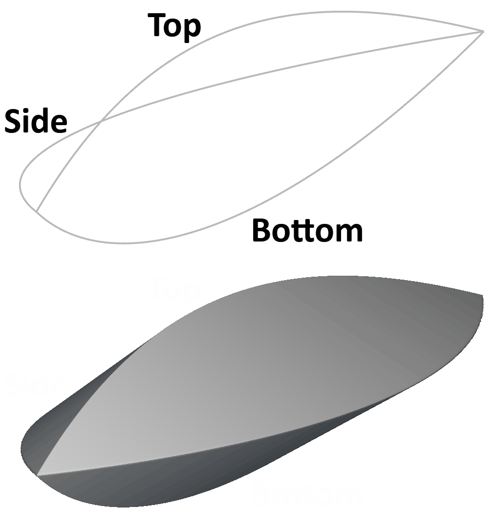
We'll begin by creating the top, bottom, and side splines to guide our fuselage surfaces. These will define the fundamental shape and proportions of our aircraft body, establishing the overall silhouette from multiple viewing angles. Think of these splines as the wireframe skeleton of your fuselage—together, they create a three-dimensional cage that will guide your surface creation.
In this example, we use **Spline by Control Points**, but you can use any curve creation technique you choose (ensuring your individual splines are coplanar). The key is ensuring your guide curves maintain smooth, fair shapes without unwanted inflection points that could create surface irregularities in your final fuselage geometry.
## 2. Distance from Central Axis
After creating our side, top, and bottom splines, we'll establish a *Central Axis* that represents the centerline of the fuselage. We'll use the x-axis as our longitudinal reference line.
Next, we need to determine how far each of our guide curves deviates from this *Central Axis* using the **Distance to Curve from Axis** block. This block requires three inputs: our curves, our axis, and the perpendicular direction we want to measure.
For the *Side* spline, we'll measure along the positive y-direction to capture the lateral displacement.
For the *Top* spline, we'll measure in the positive z-direction since it falls above our centerline.
For the *Bottom* spline, we measure in the negative z-direction since it falls below our centerline.
These distance fields will serve as the foundation for blending our guide curves into smooth fuselage surfaces, with each field representing how the surface should bulge outward from the central axis in its respective direction.
Feel free to follow the video below to set these fields up.
After creating our side, top, and bottom splines, we'll want to set a central axis that represents the centerline of the fuselage. We'll use the x-axis as the vector that'll drive this.
Next, we want to determine the difference from the axis that each of our curves are. We'll use the **Distance to Curve from Axis** block where we input our curves, our central axis, and the perpendicular direction we want to measure. So for our side spline, we'll measure along the y direction, which will give us a distance that looks something like this. I'll change my colormap on my Field Viewer to implicit and add our isolines, and I get this field as my result.
I'll do the same thing for my distance to top and my distance to bottom spline, making sure to adjust my direction for each of them. Note that for the top curve, we'll measure our direction in the positive Z. And for the bottom, we'll measure in the negative since the bottom curve will fall underneath our central axis.
## 3. Conic Sections
Now that we've established the distance fields from our *Central Axis*, we can feed them into **Conic** blocks to generate the top and bottom surfaces of our fuselage. The conic surface creates smooth, controlled blending among three defining points, making it ideal for aircraft fuselage geometry.
We'll use **Vector Field from Components** blocks to define *Points 1*, *2*, and *3* of our conic.
For the *Bottom* surface:
* *Point 1* uses our distance to side field as the X component (with Y and Z at zero)
* *Point 2* places the distance to bottom field multiplied by -1 in the Y component to position the surface below the XY plane
* *Point 3* mirrors *Point 1* by multiplying the *Distance to Side* field by -1 for the X component. Setting the *Rho* parameter to 1 creates a circular arc between these points
* *Coordinate Space* defines the X, Y, and Z reference frame for the entire operation.
The *Top* surface follows an identical setup, except *Point 2* uses the positive distance to top field instead of the bottom field.
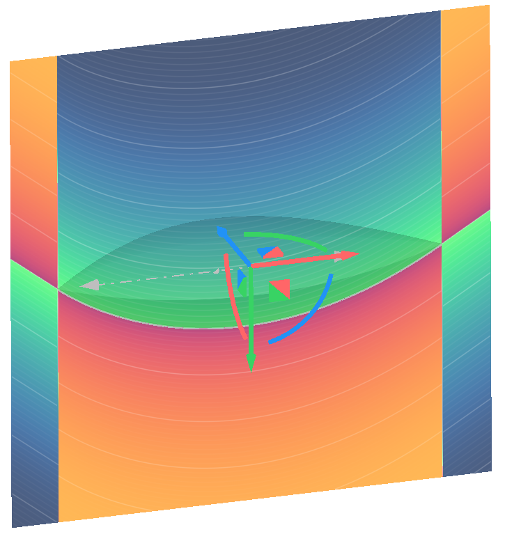
This gives us a *Bottom* field like this…
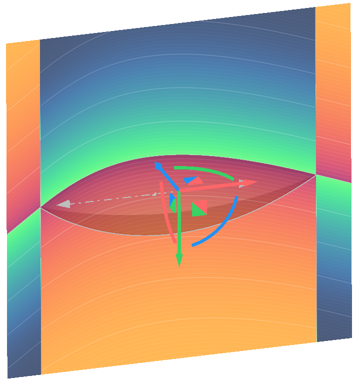
…and a top field like this.
This approach ensures both the top and bottom surfaces blend smoothly from the centerline outward to the side curves, creating the bulbous cross-section of the fuselage while maintaining precise control over the shape progression along the longitudinal axis.
Feel free to watch the video below for a more in-depth walkthrough of this setup.
Now that we've established our distance fields from our central axis, we can feed them into **Conic** blocks to generate the top and bottom surfaces of our fuselage. To do this, we'll drive *Points 1*, *2*, and *3* with the **Vector Field from Components** blocks. For the bottom surface of our fuselage, Point 1 will be a vector field whose X component is the distance to side field we evaluated in the previous section. Our Y and Z will remain at zero.
For *Point 2*, our X and Z will be zero, and our Y will be the distance to bottom field multiplied by -1. This will ensure that our surface falls underneath the XY plane in the negative Z direction. And for *Point 3*, we'll use the mirrored version of our distance to side. So for our X, we'll use a **Multiply** block with our distance to side and -1. We'll again leave our Y and Z at zero. Our row can be any value between 0 and 1, so we'll set it at 1 in this case. Finally, add a coordinate space for our X, Y, and Z. We'll just pull planes from our frame variable that looks like this.
Viewing the field of this bottom surface and adjusting the field viewer size and center, we can view our resulting distance field. This is going to establish the bottom surface of our fuselage. We'll follow a similar setup for our top surface, again pulling in our positive and negative distance to side. Instead of our distance to bottom in our *Point 2*, we'll use our positive distance to top. We'll use the same coordinate space and see this resulting field.
## **4. Bounds**
Now we've established conics to represent the top and bottom surfaces of our fuselage. To convert these distance fields into implicit geometry, we'll establish bounds and use a series of booleans to isolate and union our fields.
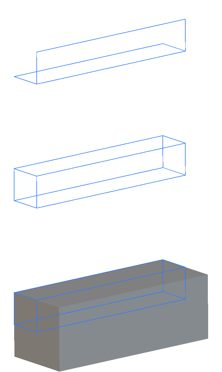
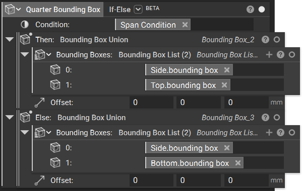
We begin by generating a bounding box that isolates our fuselage geometry. We will do this by combining the 2D bounding boxes from our *Side* and *Top* or *Side* and *Bottom* splines using the **Bounding Box Union** custom block below. This outputs a *Quarter Bounding Box* whose properties we then use in a **Box from Corners** block to generate a *Full Bounding Box*.
**Downloadable Files:**
[Bounding Box Union.ntop](https://storage.googleapis.com/files-learn/Courses/Aircraft%20Modeling/Bounding%20Box%20Union.ntop)
*This file was last updated in nTop 5.30.2*
Since our guide splines may have different spans in the positive and negative z-directions, we need an intelligent approach to capture the full extent of our design.
Using **If-Else** blocks, we compare the z-span of our top and bottom splines through their bounding box span properties, then conditionally output either a top or bottom quadrant bounding box depending on which spline extends further from the centerline. This ensures our final bounding box always encompasses the largest extent of our fuselage geometry.
We then feed similar logic into the *Full Bounding Box* creation to generate the full bounds.
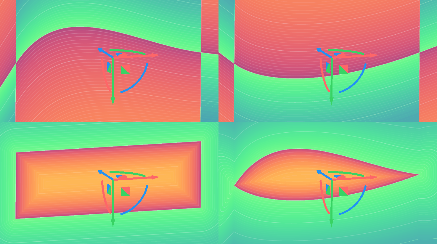
The final step combines our conic fields through boolean operations. We intersect our *Top* field with the negative of our *Bottom* field, then intersect this result with our *Full Bounding Box*. This creates a fully enclosed negative field that represents our complete fuselage geometry, with the bounding box eliminating any unwanted field extensions beyond our intended design space.
Take a look at the walkthrough below to understand the logic for bounding box creation and the boolean operations to generate the final implicit body.
Now we've established conics to represent the top and bottom surfaces of our fuselage. To convert these distance fields into implicit geometry, we'll establish bounds and use a series of boolean operations to isolate and union our fields. We begin by generating a bounding box that isolates a certain portion of our fuselage.
We'll isolate these portions one quarter at a time. Since each of our splines lies on the XY and the XZ planes, the side and the top, and the side and the bottom splines, will generate 3D bounding boxes with each of their 2D bounding boxes connected to one another. If we were to take this quarter bounding box and repeat it in each of our four quadrants to make a full bounding box, we could take that bounding box and feed it into our final body to generate our fuselage.
But say the span of our bottom spline is actually larger than the span of our top spline. In that case, our full bounding box wouldn't actually capture the entire geometry we want to create. Therefore, we can use an **If-Else** block to create our ideal bounding box. To do this, we can drag the span in the Z direction from the top and the bottom splines that we created. These will exist in our properties under **Bounding Box Span** and Y and Z.
We make these into variables for visibility and we can feed them into a **Greater Than** block to output a true or false for our span condition. We feed that boolean output into our condition in an **If-Else** block. Then if our top spline has a larger span in the Z direction, we output a bounding box in our top quadrant. And if our bottom spline has a larger Z-span, we output a bounding box in our negative Z quadrant. Since right now our top spline is larger, this **If-Else** block will output our top quadrant.
We'll use another **If-Else** block with that same span condition to then output our fully mirrored box. Our top spline being bigger, and we'll take that quarter **Bounding Box Max Point** and generate a second point that outputs this box from corners.
If instead of our top spline having the larger Z, our bottom Z were larger, giving us a false span condition, our quarter bounding box will output our bottom quadrant, and our full bounding box will look like this. We set that full bounding box by taking this point from our quarter bounding box and generating a second point using math blocks and our quarter bounding box properties.
Then in our final fuselage variable with our conic field set as well as our bounding box, we can use a **Boolean Intersect** block to intersect the fields of our top conic and the negative of our bottom conic. Scrolling up in our workflow, we can do these fields. The top from the side.
I'll turn my transparency on so we can view our fields. Scrolling up, we can see the field of our top conic. I'll adjust its size and view it from the side. And the bottom conic will look like this.
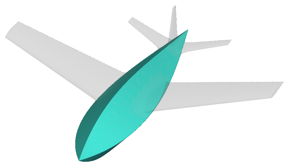
Viewing the negative of its scalar field, we see a field that looks like this. So if we intersect these two fields, we end up with this. Outside of our design space, we see these overlapping fields. So our last step is intersecting this field with our full bounding box that we created above. That generates this geometry which is a fully enclosed negative field that gives us our final fuselage.
 In this example, we use **Spline by Control Points**, but you can use any curve creation technique you choose (ensuring your individual splines are coplanar). The key is ensuring your guide curves maintain smooth, fair shapes without unwanted inflection points that could create surface irregularities in your final fuselage geometry.
## 2. Distance from Central Axis
After creating our side, top, and bottom splines, we'll establish a *Central Axis* that represents the centerline of the fuselage. We'll use the x-axis as our longitudinal reference line.
In this example, we use **Spline by Control Points**, but you can use any curve creation technique you choose (ensuring your individual splines are coplanar). The key is ensuring your guide curves maintain smooth, fair shapes without unwanted inflection points that could create surface irregularities in your final fuselage geometry.
## 2. Distance from Central Axis
After creating our side, top, and bottom splines, we'll establish a *Central Axis* that represents the centerline of the fuselage. We'll use the x-axis as our longitudinal reference line.
 Next, we need to determine how far each of our guide curves deviates from this *Central Axis* using the **Distance to Curve from Axis** block. This block requires three inputs: our curves, our axis, and the perpendicular direction we want to measure.
For the *Side* spline, we'll measure along the positive y-direction to capture the lateral displacement.
Next, we need to determine how far each of our guide curves deviates from this *Central Axis* using the **Distance to Curve from Axis** block. This block requires three inputs: our curves, our axis, and the perpendicular direction we want to measure.
For the *Side* spline, we'll measure along the positive y-direction to capture the lateral displacement.
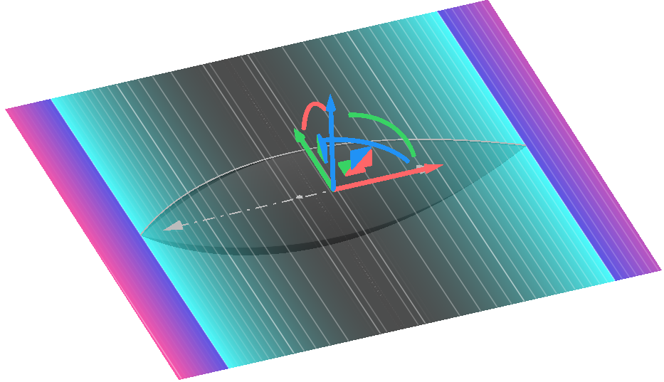 For the *Top* spline, we'll measure in the positive z-direction since it falls above our centerline.
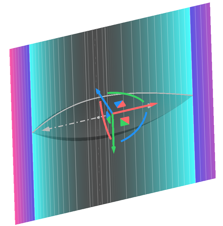 For the *Bottom* spline, we measure in the negative z-direction since it falls below our centerline.
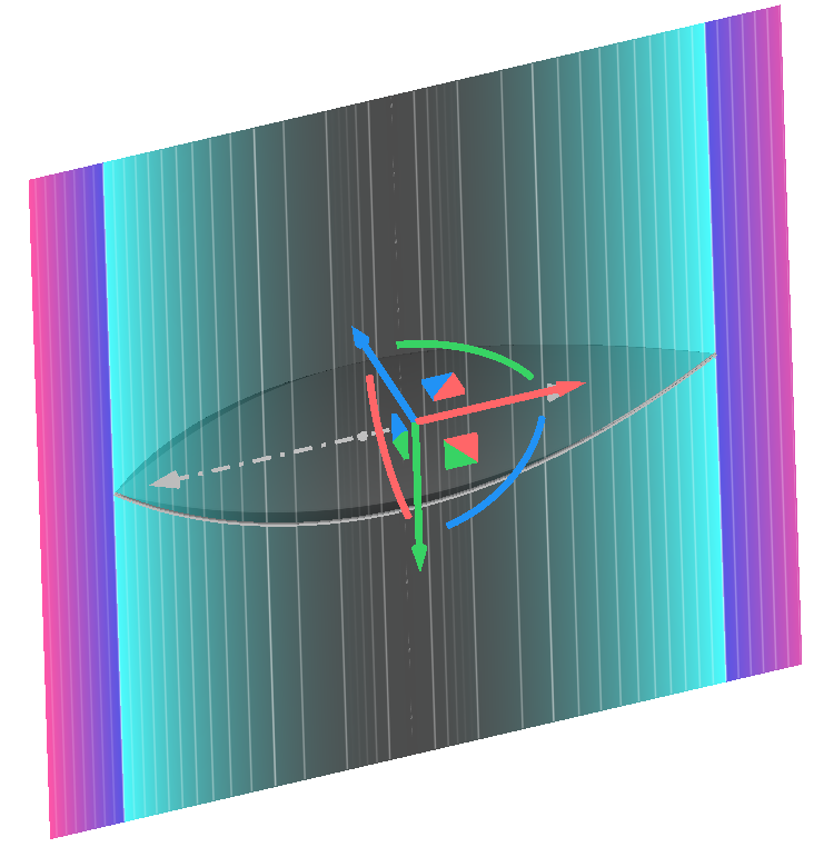 These distance fields will serve as the foundation for blending our guide curves into smooth fuselage surfaces, with each field representing how the surface should bulge outward from the central axis in its respective direction.
Feel free to follow the video below to set these fields up.
These distance fields will serve as the foundation for blending our guide curves into smooth fuselage surfaces, with each field representing how the surface should bulge outward from the central axis in its respective direction.
Feel free to follow the video below to set these fields up.
 The *Top* surface follows an identical setup, except *Point 2* uses the positive distance to top field instead of the bottom field.
This gives us a *Bottom* field like this…
The *Top* surface follows an identical setup, except *Point 2* uses the positive distance to top field instead of the bottom field.
This gives us a *Bottom* field like this…
 …and a top field like this.
 This approach ensures both the top and bottom surfaces blend smoothly from the centerline outward to the side curves, creating the bulbous cross-section of the fuselage while maintaining precise control over the shape progression along the longitudinal axis.
Feel free to watch the video below for a more in-depth walkthrough of this setup.
This approach ensures both the top and bottom surfaces blend smoothly from the centerline outward to the side curves, creating the bulbous cross-section of the fuselage while maintaining precise control over the shape progression along the longitudinal axis.
Feel free to watch the video below for a more in-depth walkthrough of this setup.
 **Downloadable Files:**
[Bounding Box Union.ntop](https://storage.googleapis.com/files-learn/Courses/Aircraft%20Modeling/Bounding%20Box%20Union.ntop)
*This file was last updated in nTop 5.30.2*
Since our guide splines may have different spans in the positive and negative z-directions, we need an intelligent approach to capture the full extent of our design.
Using **If-Else** blocks, we compare the z-span of our top and bottom splines through their bounding box span properties, then conditionally output either a top or bottom quadrant bounding box depending on which spline extends further from the centerline. This ensures our final bounding box always encompasses the largest extent of our fuselage geometry.
We then feed similar logic into the *Full Bounding Box* creation to generate the full bounds.
**Downloadable Files:**
[Bounding Box Union.ntop](https://storage.googleapis.com/files-learn/Courses/Aircraft%20Modeling/Bounding%20Box%20Union.ntop)
*This file was last updated in nTop 5.30.2*
Since our guide splines may have different spans in the positive and negative z-directions, we need an intelligent approach to capture the full extent of our design.
Using **If-Else** blocks, we compare the z-span of our top and bottom splines through their bounding box span properties, then conditionally output either a top or bottom quadrant bounding box depending on which spline extends further from the centerline. This ensures our final bounding box always encompasses the largest extent of our fuselage geometry.
We then feed similar logic into the *Full Bounding Box* creation to generate the full bounds.
 The final step combines our conic fields through boolean operations. We intersect our *Top* field with the negative of our *Bottom* field, then intersect this result with our *Full Bounding Box*. This creates a fully enclosed negative field that represents our complete fuselage geometry, with the bounding box eliminating any unwanted field extensions beyond our intended design space.
 Take a look at the walkthrough below to understand the logic for bounding box creation and the boolean operations to generate the final implicit body.