> ## Documentation Index
> Fetch the complete documentation index at: https://docs.ntop.com/llms.txt
> Use this file to discover all available pages before exploring further.
# Combustion Chamber
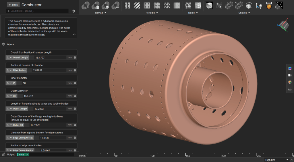
This lesson demonstrates how to use parametrized polylines and profiles in nTop to design a combustion chamber. You will learn best practices for creating complex arrays of holes and leveraging field modeling to ensure high-performance geometry.
 **Downloadable File:**
[Parametric Combustor.ntop](https://storage.googleapis.com/files-learn/Courses/Turbomachinery%20Design/Parametric%20Combustor.ntop)
[*Report File Issue*](https://docs.google.com/forms/d/1Ev9UFCZGo1aefglpX6E8sQ6Hr-Y6ILhGSZxE3paCqy4/edit)
*This file was last updated in nTop 5.37.3*
## 1. Generate the Main Body
Building a clean signed distance field (SDF) for an axisymmetric part starts with a well-defined profile.
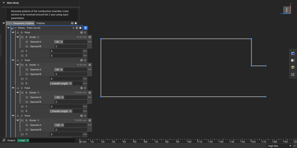
**Define the Profile:** Create a side profile of the combustor using a Polyline block. Use input parameters to drive the coordinates of each point.
*You can use similar techniques to parametrize control points for splines.*
**Downloadable File:**
[Parametric Combustor.ntop](https://storage.googleapis.com/files-learn/Courses/Turbomachinery%20Design/Parametric%20Combustor.ntop)
[*Report File Issue*](https://docs.google.com/forms/d/1Ev9UFCZGo1aefglpX6E8sQ6Hr-Y6ILhGSZxE3paCqy4/edit)
*This file was last updated in nTop 5.37.3*
## 1. Generate the Main Body
Building a clean signed distance field (SDF) for an axisymmetric part starts with a well-defined profile.
**Define the Profile:** Create a side profile of the combustor using a Polyline block. Use input parameters to drive the coordinates of each point.
*You can use similar techniques to parametrize control points for splines.*
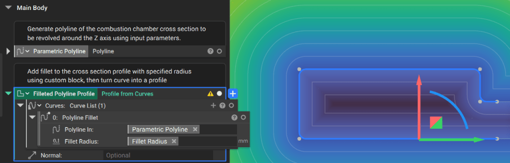
 Apply a fillet to the polyline using the **Polyline Fillet** custom block and convert the curve into a Profile. Using an open profile ensures a clean field that projects predictably beyond the open ends.
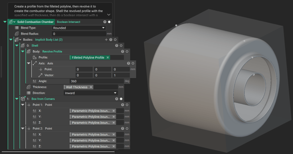
 Use the **Revolve Profile** block around the Z-axis to create solid geometry. Apply a **Shell** block to establish the specified wall thickness.
Because the start and end lines of the profile are parallel, the resulting implicit body extends to infinity. Perform a **Boolean Intersect** with a box representing the design domain to trim the body to its final size.
Use the **Revolve Profile** block around the Z-axis to create solid geometry. Apply a **Shell** block to establish the specified wall thickness.
Because the start and end lines of the profile are parallel, the resulting implicit body extends to infinity. Perform a **Boolean Intersect** with a box representing the design domain to trim the body to its final size.
 ## 2. Generate the Cutout Tools
Create the geometry used to “drill” the cooling and intake holes through the chamber walls.
Generate “infinite” **Cylinder** blocks based on your input parameters. Combine these using **Boolean Union** and then use the **Polar Array Body** block to position them around the chamber.
## 2. Generate the Cutout Tools
Create the geometry used to “drill” the cooling and intake holes through the chamber walls.
Generate “infinite” **Cylinder** blocks based on your input parameters. Combine these using **Boolean Union** and then use the **Polar Array Body** block to position them around the chamber.
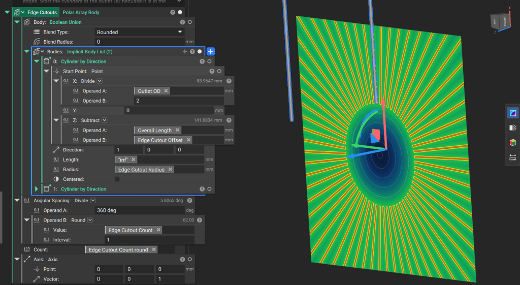 ***Tip:** Rendering highly complex or “infinite” fields can be computationally taxing. Utilize the **Field Viewer** (Hotkey: **F**) or the **Precise Render** (Ctrl + H) feature to validate the geometry and see an accurate snapshot of the design.*
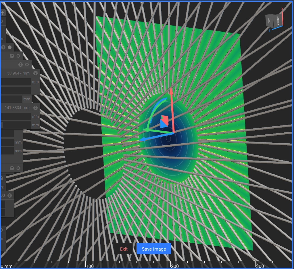 1. Generate an array of points along the Z-axis where the cutouts are required.
2. Create an array two elements longer than necessary, then remove the first and last elements to ensure correct spacing.
3. Create a corresponding array of radii for the cutouts based on your minimum and maximum specifications.
1. Generate an array of points along the Z-axis where the cutouts are required.
2. Create an array two elements longer than necessary, then remove the first and last elements to ensure correct spacing.
3. Create a corresponding array of radii for the cutouts based on your minimum and maximum specifications.
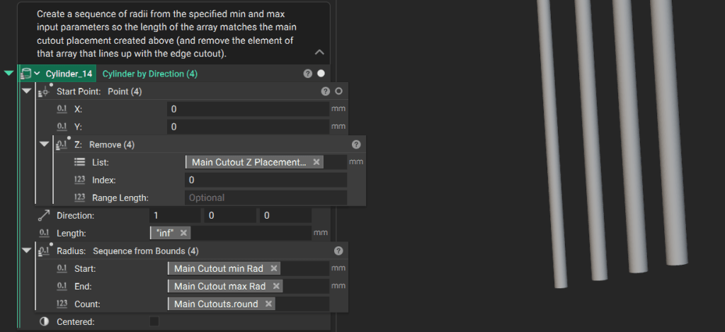 **Tip:** *You can input a list of values to a block that typically produces one implicit body to produce a list of implicit bodies.* Learn more about [working with lists here](https://support.ntop.com/hc/en-us/articles/360046264933-How-to-work-with-lists)*.*
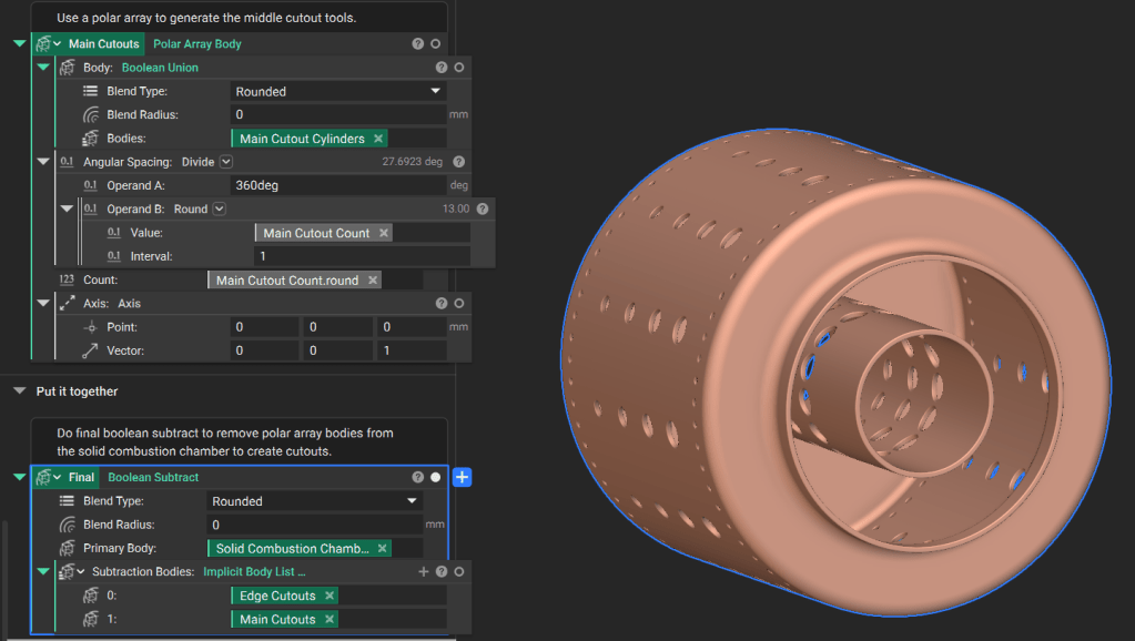
Use a **Polar Array Body** block to create the final collection of cutout tools.
## 3. Final Assembly and Output
Perform a **Boolean Subtract** to remove the cutout tools from the solid combustion chamber body.
To use this notebook in other workflows, drag the final implicit body variable into the **Output** section at the bottom of the notebook and move design parameters to the **Inputs** section at the top.
**Tip:** *You can input a list of values to a block that typically produces one implicit body to produce a list of implicit bodies.* Learn more about [working with lists here](https://support.ntop.com/hc/en-us/articles/360046264933-How-to-work-with-lists)*.*
Use a **Polar Array Body** block to create the final collection of cutout tools.
## 3. Final Assembly and Output
Perform a **Boolean Subtract** to remove the cutout tools from the solid combustion chamber body.
To use this notebook in other workflows, drag the final implicit body variable into the **Output** section at the bottom of the notebook and move design parameters to the **Inputs** section at the top.