> ## Documentation Index
> Fetch the complete documentation index at: https://docs.ntop.com/llms.txt
> Use this file to discover all available pages before exploring further.
# Parametric Bladed Disk
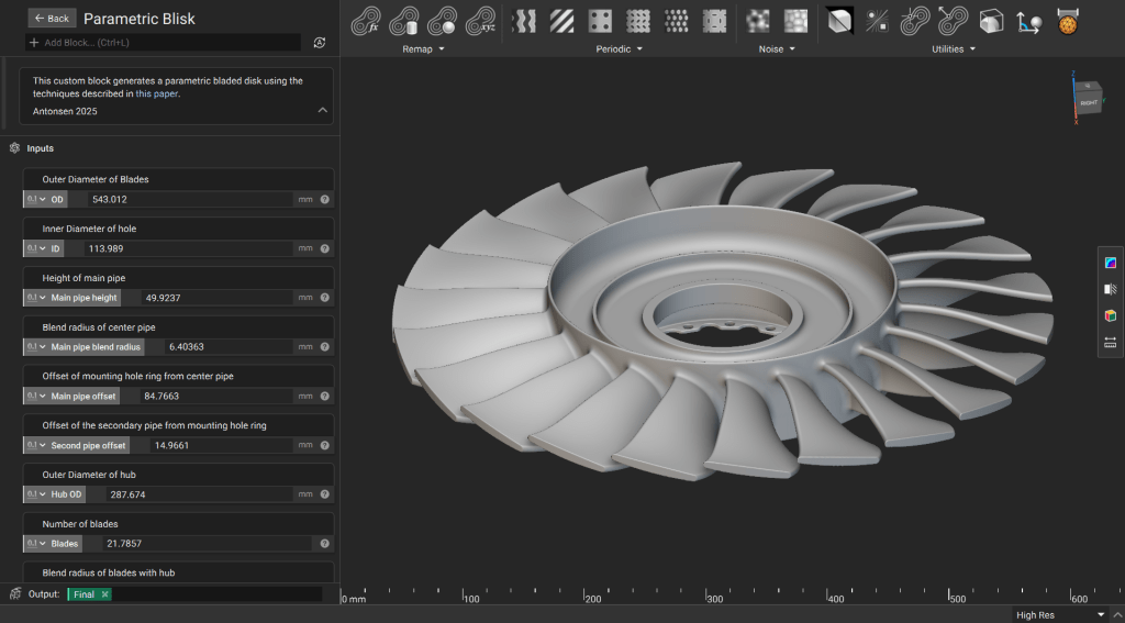
In this lesson, you will create a parametric blisk (bladed disk) designed for high-performance turbomachinery. This model replicates advanced parametrization techniques derived from the research of [Fricke et al. (2021)](https://iopscience.iop.org/article/10.1088/1757-899X/1024/1/012067). By following implicit modeling best practices, you will develop a robust, responsive custom block that maintains clean Signed Distance Functions (SDFs) across all design iterations.
 **Downloadable File:**
[Parametric Blisk.ntop](https://storage.googleapis.com/files-learn/Courses/Turbomachinery%20Design/Parametric%20Blisk.ntop)
[*Report File Issue*](https://docs.google.com/forms/d/1Ev9UFCZGo1aefglpX6E8sQ6Hr-Y6ILhGSZxE3paCqy4/edit)
*This file was last updated in nTop*5.37.3
## 1. Generate the Hub
Perform initial mathematical operations on input parameters to derive values. Use the derived values for creating primitives, then generate the main features of the hub.
We use custom blocks to help ensure efficient creation of geometry with clean fields.
**Downloadable File:**
[Parametric Blisk.ntop](https://storage.googleapis.com/files-learn/Courses/Turbomachinery%20Design/Parametric%20Blisk.ntop)
[*Report File Issue*](https://docs.google.com/forms/d/1Ev9UFCZGo1aefglpX6E8sQ6Hr-Y6ILhGSZxE3paCqy4/edit)
*This file was last updated in nTop*5.37.3
## 1. Generate the Hub
Perform initial mathematical operations on input parameters to derive values. Use the derived values for creating primitives, then generate the main features of the hub.
We use custom blocks to help ensure efficient creation of geometry with clean fields.
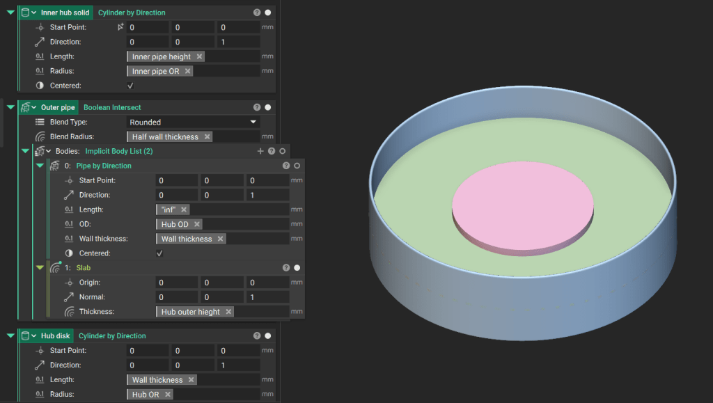 **Tip:** *When in doubt, trim as late as possible.* Trimming early in an implicit workflow could lead to unpredictable field distortions during subsequent offsets or blends.
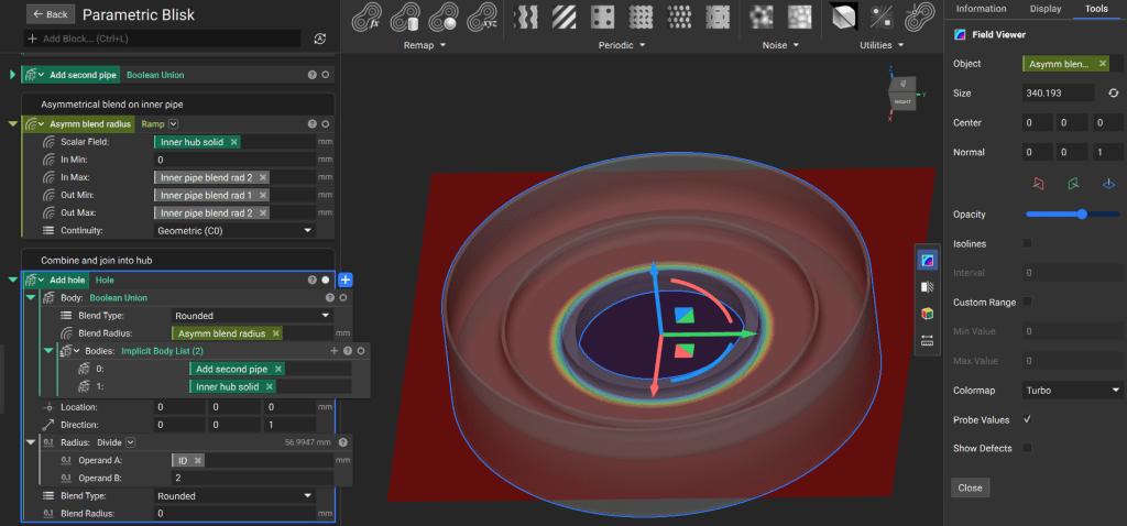
Define a custom asymmetric blend radius using a **Ramp** block. This allows for localized control over the transition between different hub features.
We continue to use custom blocks that help streamline the workflow and ensure clean signed distance functions throughout the model.
**Tip:** *When in doubt, trim as late as possible.* Trimming early in an implicit workflow could lead to unpredictable field distortions during subsequent offsets or blends.
Define a custom asymmetric blend radius using a **Ramp** block. This allows for localized control over the transition between different hub features.
We continue to use custom blocks that help streamline the workflow and ensure clean signed distance functions throughout the model.
 ## 2. Generate Flange for Hub
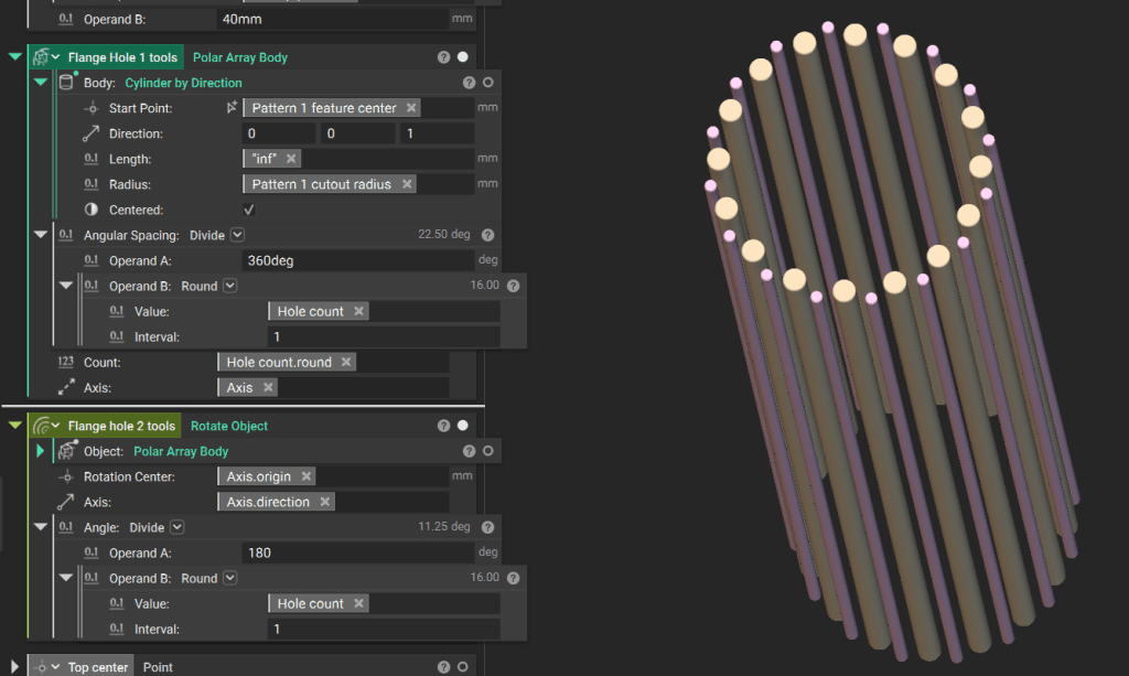
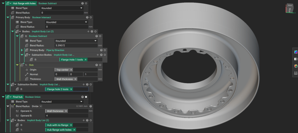
Define tools for the flange cutouts using a **Polar Array Body** of “infinite” **Cylinder** blocks. Base their placement and count on the outer diameter of the main pipe.
## 2. Generate Flange for Hub
Define tools for the flange cutouts using a **Polar Array Body** of “infinite” **Cylinder** blocks. Base their placement and count on the outer diameter of the main pipe.
 Create the final flange by subtracting the cutout tools from a pipe. Perform a **Boolean Intersect** with a **Slab** custom block to define a specific thickness within an infinite field.
Combine the finished flange with the hub using a **Boolean Union**.
Create the final flange by subtracting the cutout tools from a pipe. Perform a **Boolean Intersect** with a **Slab** custom block to define a specific thickness within an infinite field.
Combine the finished flange with the hub using a **Boolean Union**.
 ## 3. Generate the Seals
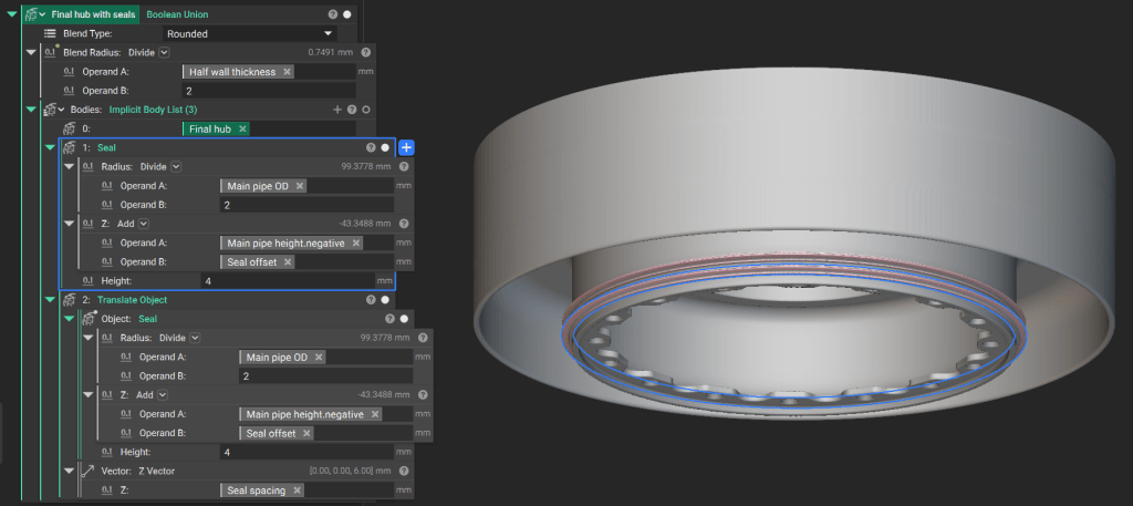
Use a custom block to generate the seal geometry around the main pipe.
Translate the seal according to the specified spacing parameters and perform a **Boolean Union** with the hub assembly.
## 3. Generate the Seals
Use a custom block to generate the seal geometry around the main pipe.
Translate the seal according to the specified spacing parameters and perform a **Boolean Union** with the hub assembly.
 ## 4. Generate the Blades
The blade geometry utilizes a **Double Circle Arc (DCA)** airfoil, standard in supersonic and transonic applications.
**Downloadable File:** [DCA Airfoil SDF.ntop](https://storage.googleapis.com/files-learn/Courses/Turbomachinery%20Design/DCA%20Airfoil%20SDF.ntop)
Generate the base SDF for the DCA airfoil. Because the inputs for the airfoil are fields, you can vary the profile spatially for advanced aerodynamic control.
## 4. Generate the Blades
The blade geometry utilizes a **Double Circle Arc (DCA)** airfoil, standard in supersonic and transonic applications.
**Downloadable File:** [DCA Airfoil SDF.ntop](https://storage.googleapis.com/files-learn/Courses/Turbomachinery%20Design/DCA%20Airfoil%20SDF.ntop)
Generate the base SDF for the DCA airfoil. Because the inputs for the airfoil are fields, you can vary the profile spatially for advanced aerodynamic control.
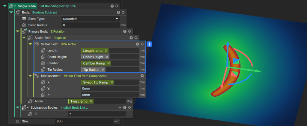 1. Model a single blade along the Z-axis using **Ramp** functions to drive geometry changes.
2. Apply a sweep using the **Displace** custom block.
3. Apply twist using the **Z Rotation** custom block.
Remove geometry below the Z-origin using a **Boolean Subtract** and add a **Bounding Box** to visualize the implicit body.
1. Model a single blade along the Z-axis using **Ramp** functions to drive geometry changes.
2. Apply a sweep using the **Displace** custom block.
3. Apply twist using the **Z Rotation** custom block.
Remove geometry below the Z-origin using a **Boolean Subtract** and add a **Bounding Box** to visualize the implicit body.
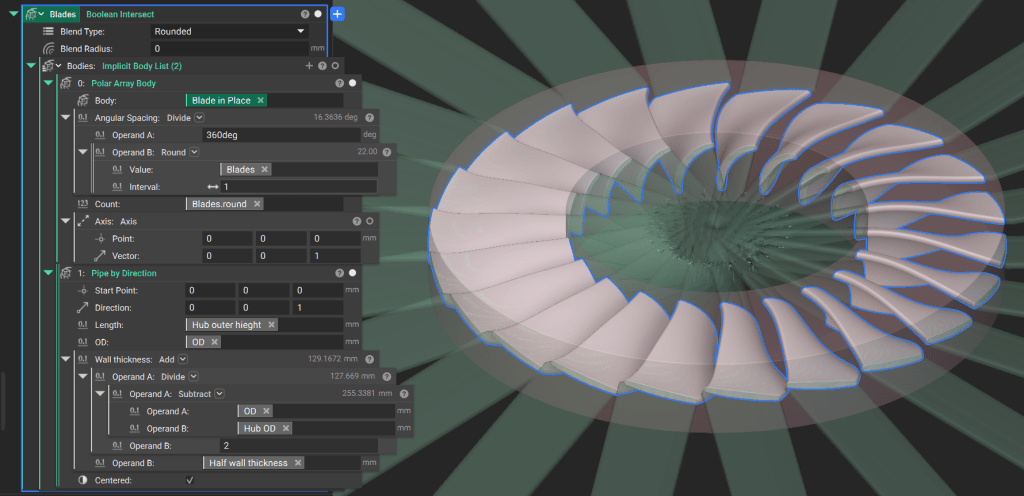
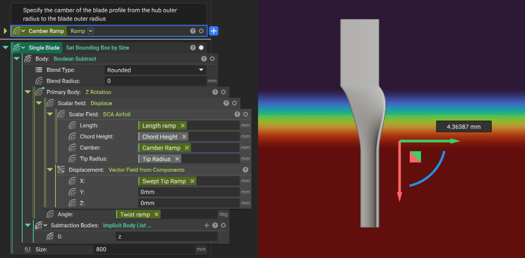 Rotate the single blade into position around the Y-axis, and use the **Polar Array Body** block to generate the required number of blades. Trim the blades to their final domain using a **Boolean Intersect** with a pipe.
 ## 5. Final Assembly
Perform a final **Boolean Union** between the blades and the hub.
Utilize field manipulation to ensure the blend radius is *0* within the hub and transitions to the specified value only at the intersection of the blades and the hub surface. This prevents internal “bulging” that occurs when a positive blend radius is applied inside solid geometry.
## 5. Final Assembly
Perform a final **Boolean Union** between the blades and the hub.
Utilize field manipulation to ensure the blend radius is *0* within the hub and transitions to the specified value only at the intersection of the blades and the hub surface. This prevents internal “bulging” that occurs when a positive blend radius is applied inside solid geometry.
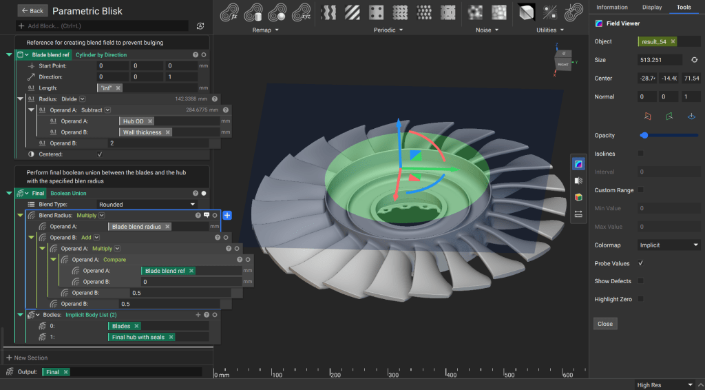 As with the other lesson, we will create a custom block for Parameteric Bladed Disk. Ensure all critical design parameters (e.g. blade count, twist rate, hub diameter) are moved to the **Inputs** section. Drag the **Final Solid** variable into the **Output** section.