> ## Documentation Index
> Fetch the complete documentation index at: https://docs.ntop.com/llms.txt
> Use this file to discover all available pages before exploring further.
# Parametric Housing and Component Placement
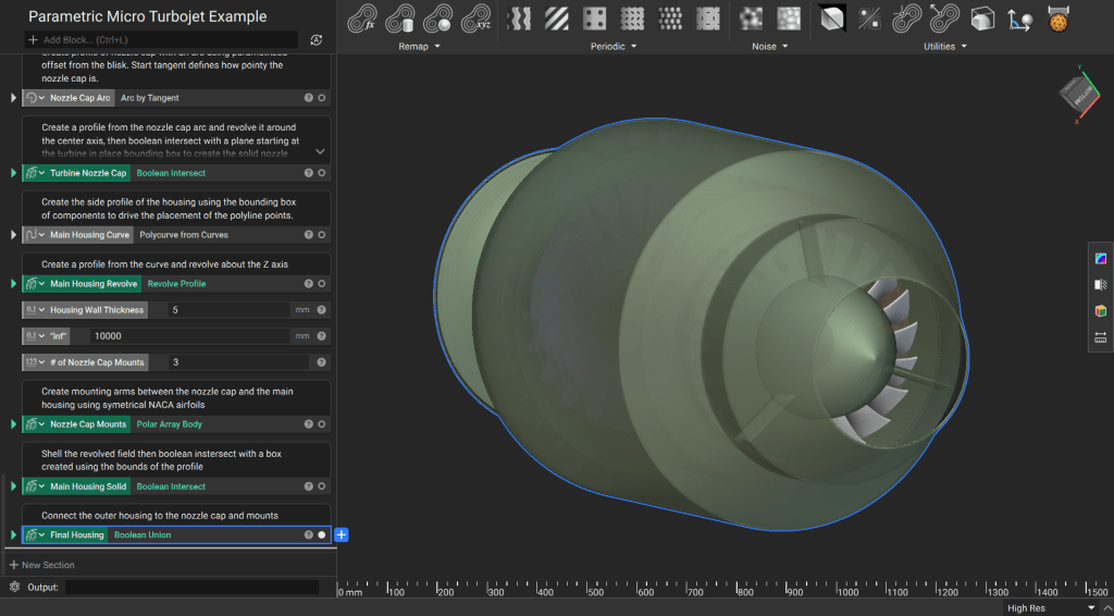
This final lesson demonstrates how to assemble each component generated with your **Custom Blocks** into a cohesive system. You will learn to use bounding box properties for relative placement, create a parametric housing, and integrate mounting struts to complete the micro turbojet assembly.
 **Downloadable Files:**
* [Parametric Micro Turbojet Example.ntop](https://storage.googleapis.com/files-learn/Courses/Turbomachinery%20Design/Parametric%20Micro%20Turbojet%20Example.ntop)
* [Turbopump Wedge Diffuser.ntop](https://storage.googleapis.com/files-learn/Courses/Turbomachinery%20Design/Turbopump%20Wedge%20Diffuser.ntop)
* [Turbo Guide Vanes.ntop](https://storage.googleapis.com/files-learn/Courses/Turbomachinery%20Design/Turbo%20Guide%20Vanes.ntop)
*These files were last updated in nTop*5.37.3
## 1. Move Components into Place
In a parametric assembly, component locations should reference a common origin or the dimensions of adjacent parts to ensure the model updates correctly when parameters change.
**Establish a Reference Point:** The **Impeller** custom block generates the base of the impeller at the origin (0, 0, 0). All subsequent components use this point as their primary reference.
**Capture Tolerances:** Use variables and basic math to define fits. For example, set the **Impeller Max Radius** as a variable and add a tolerance value to drive the **Wedge Diffuser Inner Radius**.
Use the **Translate Object** block to position the **Wedge Diffuser**. Since the original block centers the diffuser on the origin, translate it along the Z-axis by half the base plate thickness plus an offset tolerance.
**Tip:** Access the **Bounding Box** properties of a block (such as the `min` or `max` points) to drive placement
**Downloadable Files:**
* [Parametric Micro Turbojet Example.ntop](https://storage.googleapis.com/files-learn/Courses/Turbomachinery%20Design/Parametric%20Micro%20Turbojet%20Example.ntop)
* [Turbopump Wedge Diffuser.ntop](https://storage.googleapis.com/files-learn/Courses/Turbomachinery%20Design/Turbopump%20Wedge%20Diffuser.ntop)
* [Turbo Guide Vanes.ntop](https://storage.googleapis.com/files-learn/Courses/Turbomachinery%20Design/Turbo%20Guide%20Vanes.ntop)
*These files were last updated in nTop*5.37.3
## 1. Move Components into Place
In a parametric assembly, component locations should reference a common origin or the dimensions of adjacent parts to ensure the model updates correctly when parameters change.
**Establish a Reference Point:** The **Impeller** custom block generates the base of the impeller at the origin (0, 0, 0). All subsequent components use this point as their primary reference.
**Capture Tolerances:** Use variables and basic math to define fits. For example, set the **Impeller Max Radius** as a variable and add a tolerance value to drive the **Wedge Diffuser Inner Radius**.
Use the **Translate Object** block to position the **Wedge Diffuser**. Since the original block centers the diffuser on the origin, translate it along the Z-axis by half the base plate thickness plus an offset tolerance.
**Tip:** Access the **Bounding Box** properties of a block (such as the `min` or `max` points) to drive placement
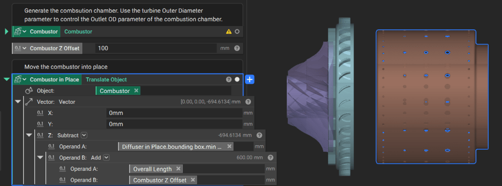
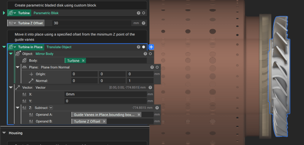
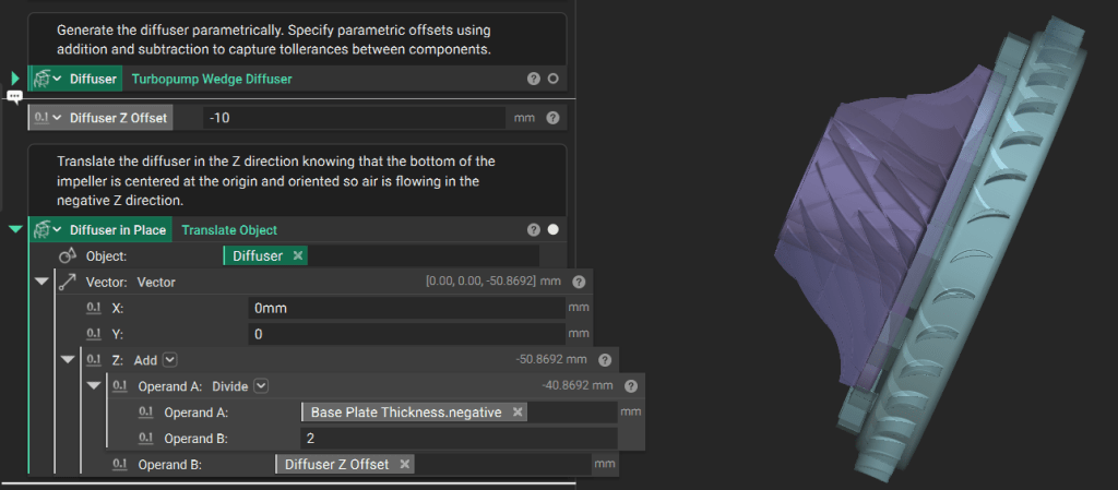 Place the **Combustor** relative to the `min Z` point of the diffuser's bounding box. Move it down by the overall length parameter plus a Z-offset.
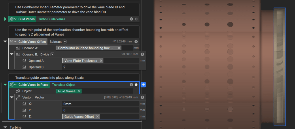
 Position the **Guide Vanes** and **Blisk** using the same logic, referencing the bounding box of the component immediately preceding them.
 ## 2. Generate the Nozzle Cap
The nozzle cap directs exhaust flow and is defined by the dimensions of the turbine wheel (**Blisk**).
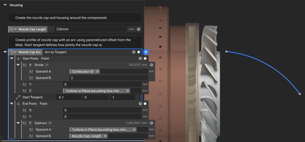
**Define the Profile:** Generate an arc for the nozzle cap side profile. Parametrize its points using the `min Z` point and inner diameter of the **Blisk**.
Modify the “pointiness” of the cap by changing the start tangent of the arc.
## 2. Generate the Nozzle Cap
The nozzle cap directs exhaust flow and is defined by the dimensions of the turbine wheel (**Blisk**).
**Define the Profile:** Generate an arc for the nozzle cap side profile. Parametrize its points using the `min Z` point and inner diameter of the **Blisk**.
Modify the “pointiness” of the cap by changing the start tangent of the arc.
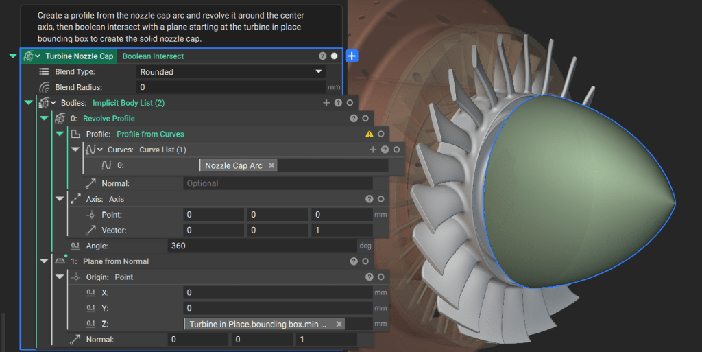
 **Create Solid Geometry:** Use the **Revolve Profile** block to sweep the arc around the Z-axis. Perform a **Boolean Intersect** with a **Plane** located at the **Blisk** `min Z` point to ensure a clean mating surface.
 ## 3. Generate the Outer Housing
The housing must encapsulate all internal components while allowing for specific wall thicknesses.
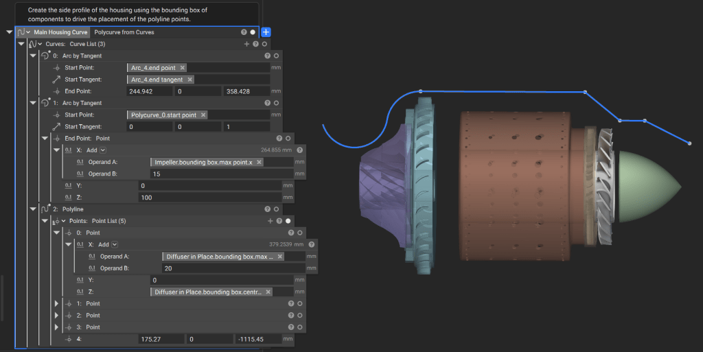
**Construct the Side Curve:** Use the **Polyline** block and arcs to create the housing profile. Parametrize these curves based on component bounding boxes plus required offsets.
**Note:** In production workflows, these curves are often driven by first-order equations governing the engine's performance requirements.
## 3. Generate the Outer Housing
The housing must encapsulate all internal components while allowing for specific wall thicknesses.
**Construct the Side Curve:** Use the **Polyline** block and arcs to create the housing profile. Parametrize these curves based on component bounding boxes plus required offsets.
**Note:** In production workflows, these curves are often driven by first-order equations governing the engine's performance requirements.
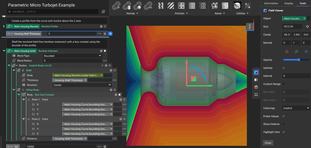
 **Revolve and Shell:**
1. Revolve the profile around the Z-axis to create an initial solid.
2. Use the **Shell** block to hollow the geometry to your specified wall thickness.
3. Finalize the geometry by performing a **Boolean Intersect** with a **Box** (generated from the side profile's bounding box) to trim any infinite fields
**Revolve and Shell:**
1. Revolve the profile around the Z-axis to create an initial solid.
2. Use the **Shell** block to hollow the geometry to your specified wall thickness.
3. Finalize the geometry by performing a **Boolean Intersect** with a **Box** (generated from the side profile's bounding box) to trim any infinite fields
 ## 4. Generate Mounts and Union Housing
Mounting struts connect the internal nozzle cap to the outer housing.
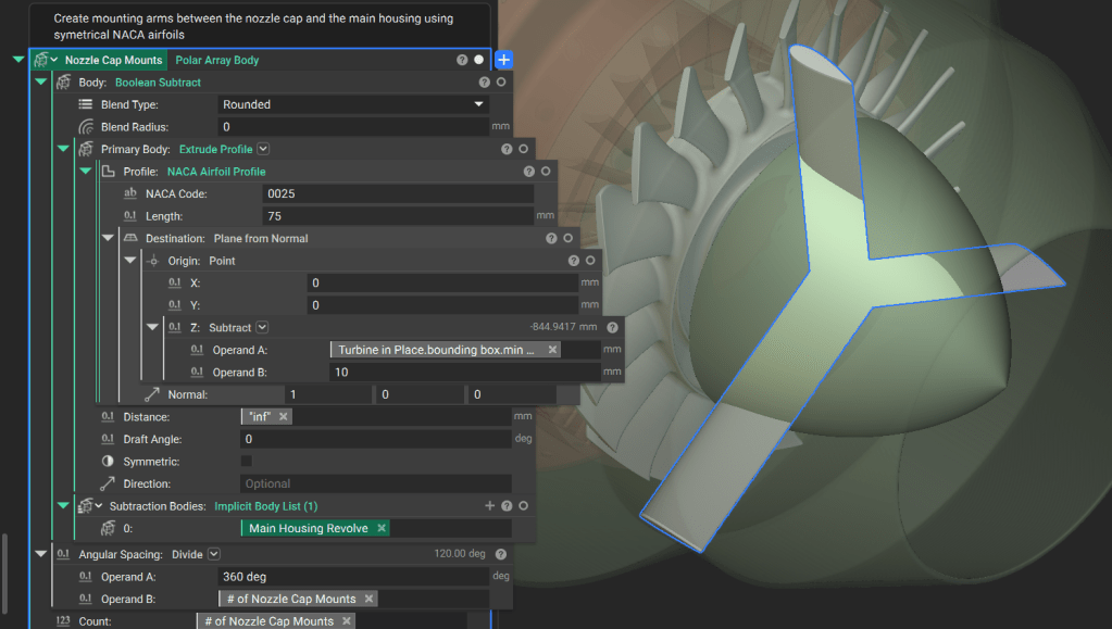
**Model Struts:** Use a **Custom Block** to generate a symmetrical 4-digit NACA airfoil profile.
**Extrude and Array:**
1. Use **Extrude Profile** to create the strut geometry.
2. Use **Boolean Subtract** to remove the portion of the struts that overlaps with the main housing field.
3. Apply a **Polar Array Body** block to create the required number of struts around the Z-axis.
## 4. Generate Mounts and Union Housing
Mounting struts connect the internal nozzle cap to the outer housing.
**Model Struts:** Use a **Custom Block** to generate a symmetrical 4-digit NACA airfoil profile.
**Extrude and Array:**
1. Use **Extrude Profile** to create the strut geometry.
2. Use **Boolean Subtract** to remove the portion of the struts that overlaps with the main housing field.
3. Apply a **Polar Array Body** block to create the required number of struts around the Z-axis.
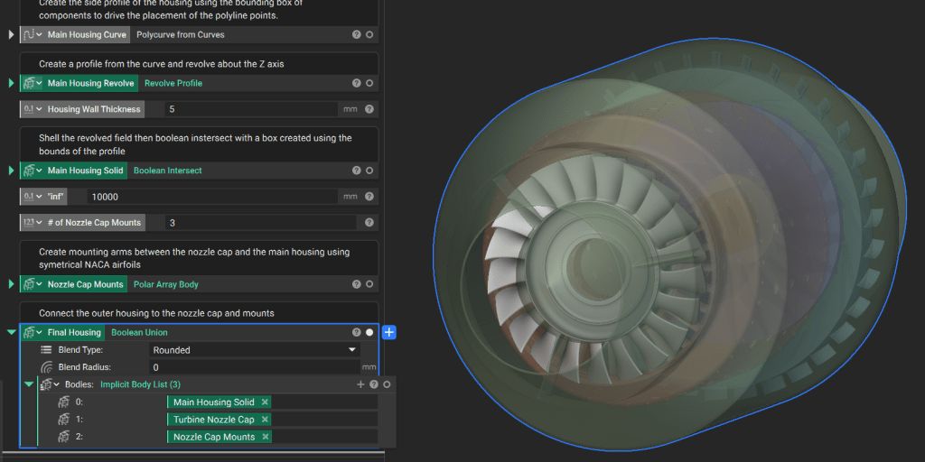
 Join the nozzle cap, struts, and outer housing using a **Boolean Union** to create the final solid engine assembly.
 Congratulations! You have completed the **Parametric Turbomachinery Design** course. You now have a modular, reusable system for exploring and optimizing micro turbojet designs.