Introduction
CAD and CAE software uses a variety of representations of shape to define and document real-world parts. If you have ever used a 3D modeling program, you’ve most likely worked with meshes, boundary representations (B-rep), or both depending on the task at hand. Although these models have their strong points, their weaknesses appear as geometry becomes more complex. nTop uses implicit modeling technology. This allows designers to focus on engineering work that matters, and spend less time with non-value-added tasks.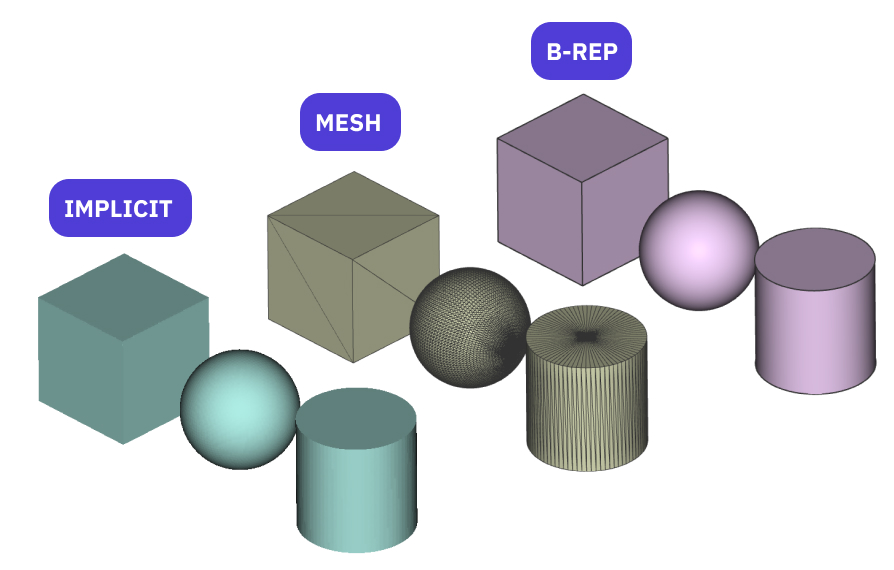
Precise B-reps
B-reps represent solids using a patchwork of faces, joined together by edges, separating a homogeneous inside from the outside. Each face can be made of geometry appropriate for its contribution to the boundary of the part, such as a plane, cylinder, or NURB surface. Common B-rep formats include STEP or native formats from well-known CAD systems such as Catia, NX, Creo, Solidworks, Rhino, and others.- One of the most popular solid modeling approaches.
- Works well for low-to-medium complexity.
- Struggles with highly detailed designs, organic shapes, scan data, lattice, porous structures, spatially varying materials, and additively manufactured parts.
- Impractical to work on when they have thousands of faces and impossible with tens of thousands of faces.
- Unreliable in some situations: booleans with tangent faces, shells with thick walls, overlapping filets.
Meshes
Mesh models are simplified B-reps where all faces (typically called “facets”) are triangles. The more curved a region of the model is, the finer the triangles must be to represent it. The data structures tend to be simpler, in part because the triangle describes each facet’s planar geometry and boundary. Common mesh formats include STL, OBJ, 3MF, and VRML.- For manufacturing, meshes tend to become impractical when they have face counts in the tens of millions.
- Converting a B-rep to a mesh is typically straightforward, but converting a mesh to B-rep involves a few more steps. In nTop, we create B-reps from meshes by converting the triangular mesh into a quad mesh first and then turn it into surfaces used in a B-rep. This enables users to bring their nTop designs into CAD programs that use B-reps.
Implicit Geometry
nTop uses a new kind of modeling technology, called implicit modeling, rather than the boundary representation (b-rep) approach used in traditional CAD systems: objects are represented by equations, not by gluing together collections of faces. The pictures below show the b-rep and implicit methods of representing a simple 2D rectangle. As you can see, the two approaches are completely different.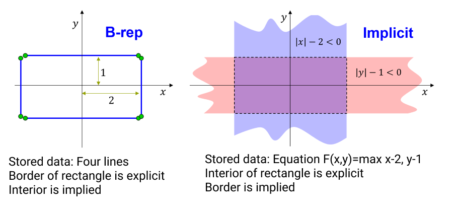 By using the implicit approach, we avoid the fragile and expensive computations that are the foundation of b-rep systems such as Catia, NX, Creo, SolidWorks, Rhino, and others.
Implicit models offer:
By using the implicit approach, we avoid the fragile and expensive computations that are the foundation of b-rep systems such as Catia, NX, Creo, SolidWorks, Rhino, and others.
Implicit models offer:
- Lightweight files due to only a minimal amount of information needed.
- Unbreakable modeling operations (offsetting, rounding, drafting, boolean operations).
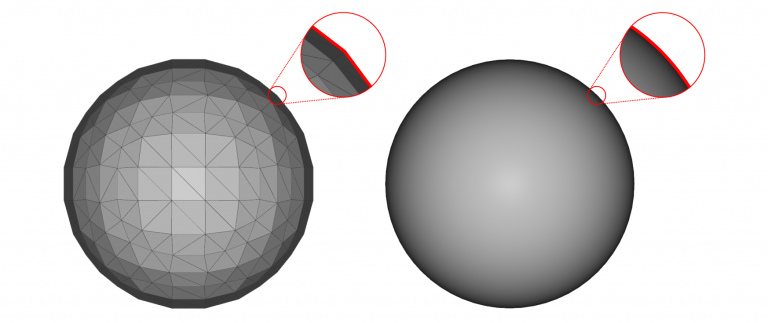 > A mesh representation compared to an implicit representation of a sphere. The mesh face count of the sphere is purposely low to exaggerate the discretization. If we increased the mesh face count to more accurately represent the sphere, the file size would also increase.