FE Model, Box, Scalar, Bool, Bool
FE Model, Box, Scalar, Bool, Bool, 1.1.0
About this Block
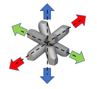
What it does: The Homogenize Unit Cell block can be used to calculate the effective mechanical and thermal properties of a unit cell. These properties, when applied to a solid volume, can be used to determine the structural and thermal performance of a lattice structure occupying this volume that is composed of this unit cell. This way, you are able to estimate the macro-level performance of the lattice geometry without meshing its complex structure. This saves time and computational effort to analyze lattice structures with a static or thermal analysis. The block functions by applying unit loads to the unit cell in the following ways : (a) Mechanical: 6 unit strain loads in the tensile (X, Y, Z) and shear (XY, XZ, YZ) directions under periodic boundary conditions to calculate the effective stiffness of the unit cell. The block calculates the 21 components Cij of the anisotropic stiffness matrix. (b) Thermal: 3 unit temperature loads in the X, Y, and Z direction under periodic boundary conditions to calculate the effective conductivity and specific heat of the unit cell. The block calculates the 6 components kij of the anisotropic thermal conductivity matrix.
  In addition to the mechanical and thermal properties, the effective density of the unit cell is also calculated.
Common uses:
In addition to the mechanical and thermal properties, the effective density of the unit cell is also calculated.
Common uses:
- Analyzing complex lattice structures.
- Exporting material properties.
Tips:
| Ignores blend lattice-wall radius.| Lattice thickness must be uniform.
| Pros | Cons |
|---|---|
| A fast method of analyzing lattices. | More setup steps. |
| Works for any type of lattice. | Least accurate option compared to using a solid element or beam element simulations. |
| Works on large and high-density lattice structures. | No edge effects. |
| No stress concentrations. |
-
The block has the following inputs :
- Unit Cell Model : This is the Simulation Model of the unit cell that has its mesh, attribute (solid) and the material property.
- Design Volume : This is the Implicit Body that envelops the boundaries of the unit cell exactly. This is typically a box. Unit cells with rounded corners are typically trimmed to fit a box.

- Tolerance : This is the search tolerance to establish a rigid connection between the periodic boundaries of the unit cell. The tolerance value should be large enough to capture the nodes on the periodic boundaries but small enough to avoid over-constraining these boundaries. A recommended value is 10% of the element size of the unit cell mesh.
- Mechanical and Thermal checkboxes : By default, the block has the Mechanical option checked to calculate the effective elastic properties. Optionally, checking the Thermal option will prompt the block to calculate the effective Thermal properties like the anisotropic conductivity and specific heat capacity of the unit cell.
-
Periodicity in all directions : While this method offers a convenient way to cut down the computational effort for large lattice structure simulation, it is best applied to situations where this lattice is periodic in all 3 orthogonal directions.
-
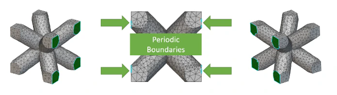
Tolerance setting : The tolerance setting defines the maximum distance between the nodes on the periodic boundaries that will be connected. Typically, the default tolerance value of 0.01mm should work for most cases, but a recommended tolerance size is about 10% of the mesh size. A method to check that the tolerance value is appropriate to capture the periodic boundaries is to increase the deformation scale of any Homogenization result. If the tolerance is right, the boundaries would deform uniformly (image on the left). If not, there would be disconnected nodes in the boundary (image on the right).
 If the tolerance value is too large, the block will report the following error : “Error in solving the linear system of equations. System is not positive definite.”
- Exporting Material properties : It is possible to export the anisotropic material properties generated by the Homogenize Unit cell block. This can be achieved through the Export Material block as described in this support article.
Example File
Example 1 - Bend Testing a Lattice Panel
 In this example, a lattice panel is tested in bending to estimate its flexural strength. Two different models of this panel are analyzed - one composed of the lattice structure and the second with a volume representing this lattice. We’ll refer to the first model as the Microstructure model and the second model as the Macrostructure model (image below).
  Assuming the microstructure model being analyzed is made out of Aluminum, the Homogenize Unit Cell block is used to estimate the effective elastic properties using Aluminum and the unit cell of the microstructure model. This block is then used as the material property input for the analysis of the macrostructure. The static analysis of the panels involves the following boundary conditions:
  Here are the x-direction longitudinal stress results of the 2 models when bent by a force of 500 N in the indicated direction:
  Here is a table summarizing the performance and results of the 2 panels:
| Model | S11 Stress, MPa | Max Displacement, mm | Mesh Time, s | Solve Time, s |
|---|---|---|---|---|
| Macromodel | 131.37 | 1.47 | 15 | 340 |
| Micromodel | 130.22 | 1.43 | 46 | 45 |
Example 2 - Thermal Analysis of a Porous Structure
 In this example, a porous structure composed of the unit cell (image above) is analyzed to estimate its thermal performance from an applied heat flux load. It is assumed that the structure is made of Aluminum. The thermal boundary conditions applied to the porous structure (and the representative macrostructure) is outlined in the following image:
  The following images illustrate the temperature distribution between the macromodel and the micromodel. Both models show a maximum temperature of around 50 K with the applied heat flux load:
  Download Example: Thermal Analysis of a Porous Structure
FE Model, Box, Scalar, Bool, Bool
Performs a numerical homogenization on an FE Model representing a unit cell of a periodic structure to estimate effective mechanical and thermal properties of an equivalent bounding volume of the unit cell. The homogenized elastic properties are computed from the displacement fields associated with six unit strain loads in the X, Y, Z, XY, XZ, YZ directions while the thermal properties are computed from the temperature fields associated with 3 unit temperature loads in the X, Y, and Z directions under periodic boundary conditions.Inputs
| Name | Type | Description |
|---|---|---|
| Unit cell model | FE Model | The fe model of unit cell. |
| Design volume | Box | The design volume to be homogenized. this will typically be the bounding geometry of the unit cell. |
| Tolerance | Scalar | The tolerance for setting periodic boundary conditions. |
| Mechanical | Bool | Select this option to calculate the elastic properties from the unit cell model. |
| Thermal | Bool | Select this option to calculate the thermal properties from the unit cell model. |
Outputs
FE Model, Box, Scalar, Bool, Bool, 1.1.0
Performs a numerical homogenization on an FE Model representing a unit cell of a periodic structure to estimate effective mechanical and thermal properties of an equivalent bounding volume of the unit cell. The homogenized elastic properties are computed from the displacement fields associated with six unit strain loads in the X, Y, Z, XY, XZ, YZ directions while the thermal properties are computed from the temperature fields associated with 3 unit temperature loads in the X, Y, and Z directions under periodic boundary conditions.Inputs
| Name | Type | Description |
|---|---|---|
| Unit cell model | FE Model | The fe model of unit cell. |
| Design volume | Box | The design volume to be homogenized. this will typically be the bounding geometry of the unit cell. |
| Tolerance | Scalar | The tolerance for setting periodic boundary conditions. |
| Mechanical | Bool | Select this option to calculate the elastic properties from the unit cell model. |
| Thermal | Bool | Select this option to calculate the thermal properties from the unit cell model. |