About this Block
What it does: Calculates displacements, strains, stresses, and reaction forces using static finite element analysis, for a given Simulation Model and set of Boundary Conditions. Common uses:- Validating designs.
- In Topology Optimization workflows to analyze the design before and after.
- Generating fields from the resulting stresses, strains, and displacement results.
- The loads are assumed to be applied slowly until the model reaches a state of equilibrium (static assumption), and the relationship between loads and displacements is assumed to be linear. The analysis neglects all inertial and damping forces.
- Boundary conditions must contain a displacement restraint for at least one node to fix the model in space and allow it to reach equilibrium.
- When the calculation is complete, a Head’s Up Display (HUD) will appear that allows you to visualize the block’s results. The block’s visibility must be on to see the results window.
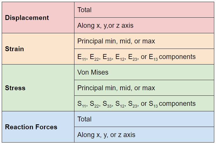
- The following metrics are viewable as 3D colormaps overlaid onto the object through the dropdown menus. You can change the min and max values in the colormap by clicking on their values, and you can change the colormap by clicking on the arrow to the top left of the scale bar.
- The “Deformation scale” controls the exaggeration of the displacement for visual inspection. The Scale Factor controls the exaggeration of the displacement for visual inspection.
- The stress, strain, and displacement results can be extracted from the Static Analysis properties by dragging them into the Notebook or into a block input. View the results with the Field Viewer (F).
- You can generate point maps from the Static Analysis block using the Von Mises Stress Point Map and Displacement Point Map block.
- If you need other point maps, you can generate your own point maps by using the Point Map block with the value input being the Evaluate Field block with a Point list. Use the same Point list as the Point input.
- It is recommended to use a Quadratic Geometric order FE Mesh with any analysis to get the most accurate results.
Example File
Download Example: Static Analysis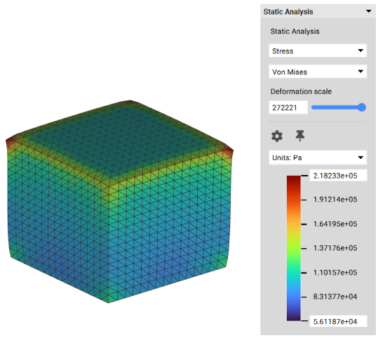
Calculate displacements, strains, stresses, and reaction forces on an FE Model subject to applied boundary conditions. The loads are assumed to be applied slowly until the model reaches a state of equilibrium, and the relationship between loads and displacements is assumed to be linear. All inertial and damping forces are neglected.
Inputs
| Name | Type | Description |
|---|---|---|
| Model | FE Model | The finite element model. |
| Load case | Boundary Condition List | The restraints and applied loads. |