Objective
This article explains the process for setting up and running a GPU-accelerated Computational Fluid Dynamics (CFD) simulation using the Aircraft Flow Analysis block to obtain aerodynamic performance data, including pressure, velocity fields, and surface forces.Applies to:
- Calculating lift, drag, and moments on wings, fuselage sections, or complete aircraft assemblies.
Procedure:
System Requirements: Requires an NVIDIA GPU for flow analysis.Note: This capability is currently only applicable to subsonic flows (speeds up to Mach 0.7).
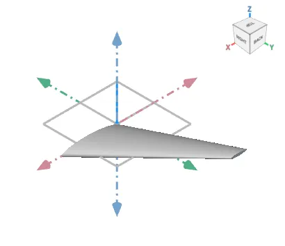
- Prepare and Orient the Geometry: Ensure your aircraft geometry is represented as an Implicit Body and is correctly oriented:
- Flow direction must be aligned with the positive X-axis.
- Starboard/right wing direction must be aligned with the Y-axis.
- Lift direction must be aligned with the Z-axis.
- Add the Aircraft Flow Analysis Block: Insert the block from the Fluids > Analysis section of the ribbon.
- Drag and drop your Implicit Body to the Aircraft Body input.
- Define Flow Parameters: Input the required freestream conditions and cell size:
- Set the Mach number (required).
- Set the Temperature (default is 288.15 K) and Pressure (default is 101325 Pa).
- Input the desired Angle of Attack (in degrees).
- Define the Cell Size.
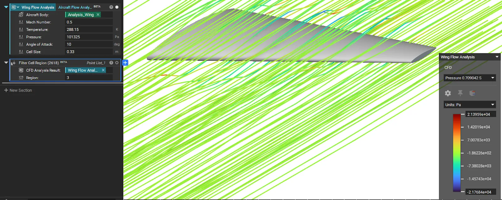
Note: Smaller cell sizes increase fidelity but require significantly more computation time.
- Analyze Results: Run the block. The simulation will run until it reaches a steady state and output a CFD Analysis Result, which you can use for post-processing, visualization, and extracting force data.
- Check Boundaries: Review the boundary conditions set by the block in the properties panel to confirm the velocity inlet and pressure outlet are correct.
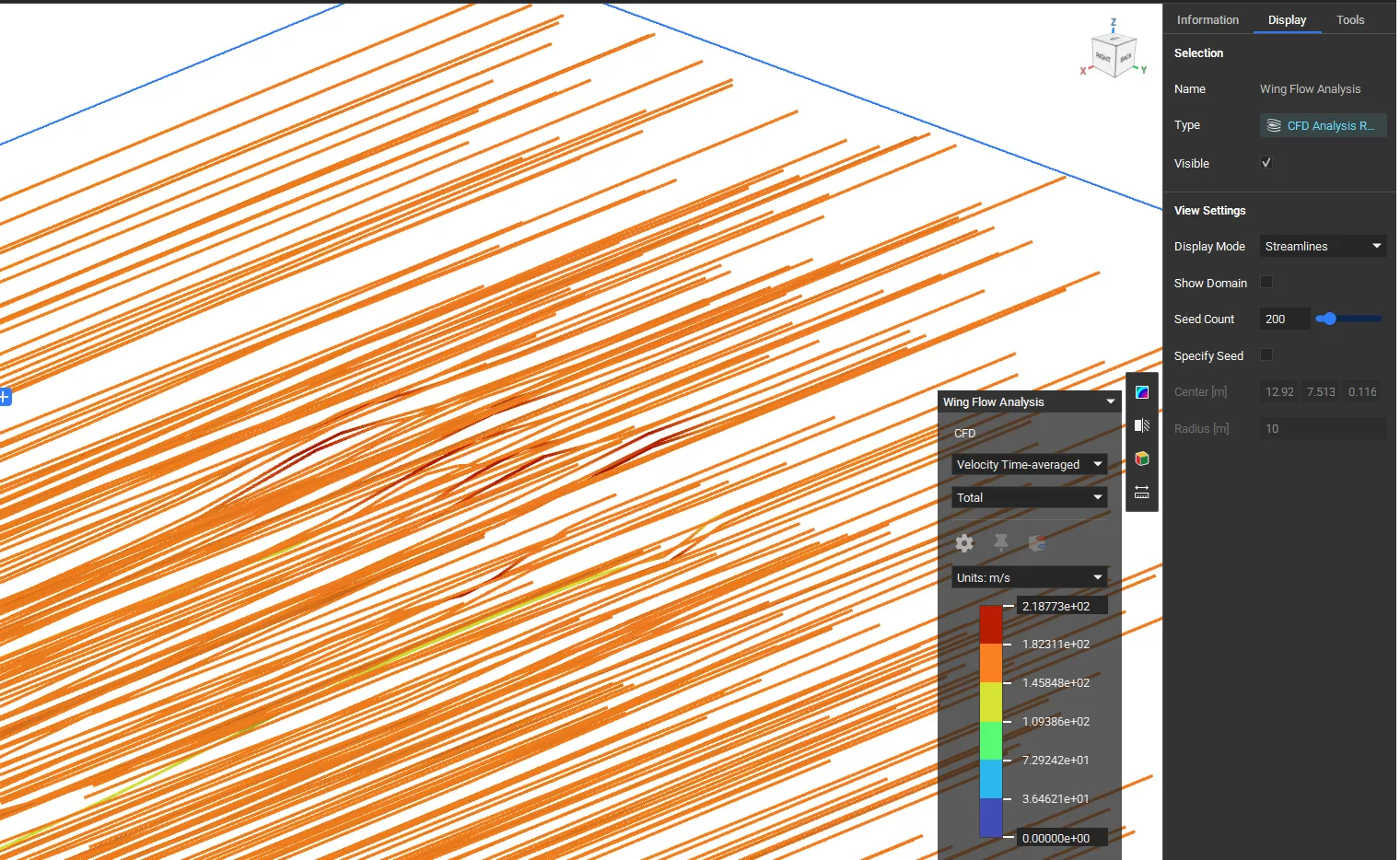
- View Streamlines: To visualize the flow field, select the result in the notebook and update its Display Mode to Streamlines in the View Settings.
 4. Extract Near-Body Data (Advanced Post-Processing): To extract data points from a specific area of the fluid domain:
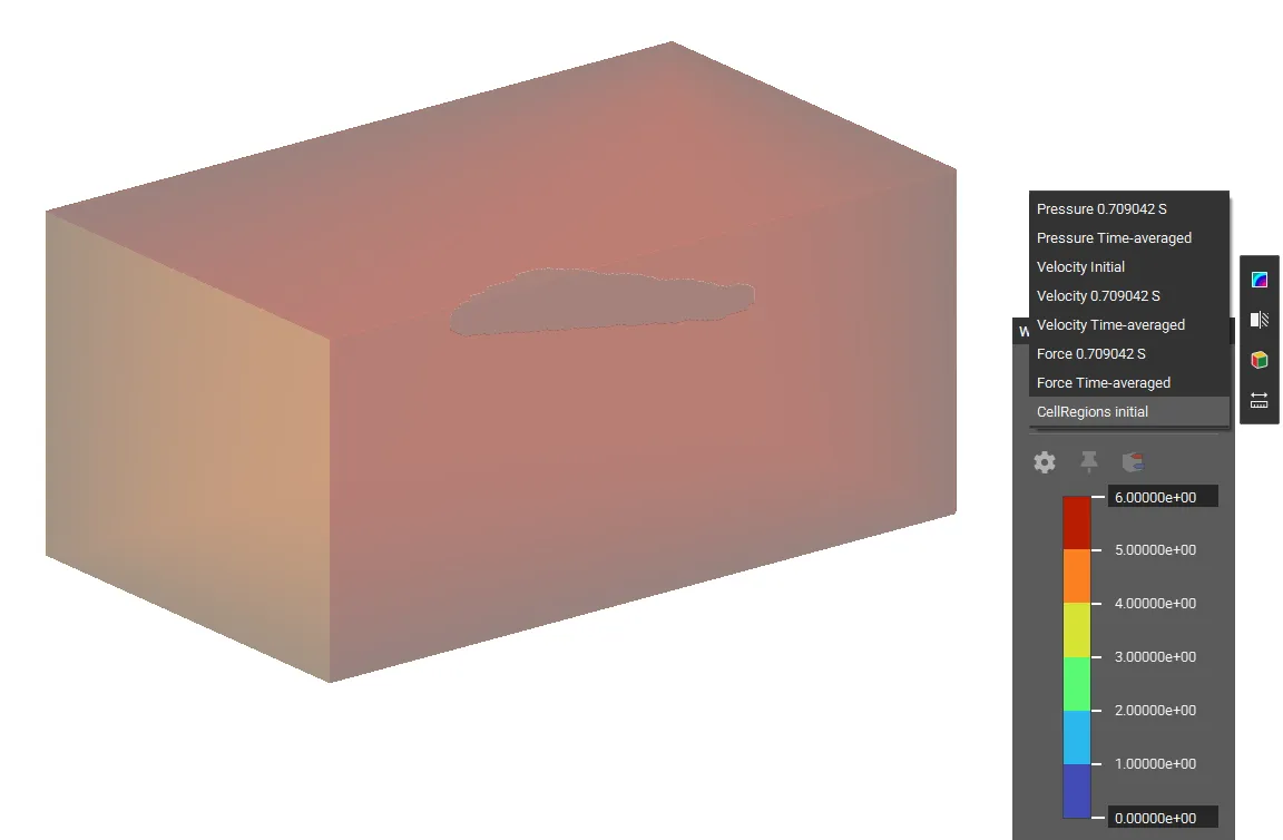
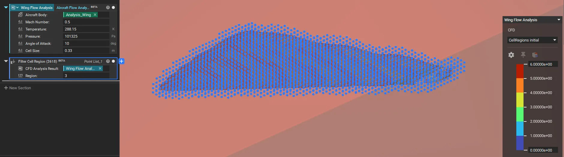
- Find Region ID: Select the Aircraft Flow Analysis block and switch the Heads-Up Display (HUD) to Cell Region to visualize and determine the identifier for the region you want to analyze (e.g., region 3 is typically the area near the aircraft body).
 - Filter Points: Add the Filter Cell Region block. Input the CFD Analysis Result and set the Region ID (e.g., 3) to generate a list of points around the aircraft body.
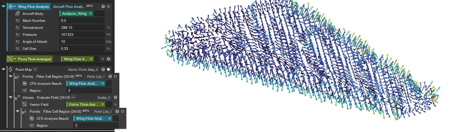
 - Evaluate Data: Use the output Point List along with the Evaluate Field block for detailed downstream analysis of pressure or velocity near the surface.
 And that’s it! You’ve successfully run an Aircraft Flow Analysis to calculate the aerodynamic forces on your design.
Are you still having issues? Contact the support team, and we’ll be happy to help!
And that’s it! You’ve successfully run an Aircraft Flow Analysis to calculate the aerodynamic forces on your design.
Are you still having issues? Contact the support team, and we’ll be happy to help!