FE Point, Boundary, FE Coupling Enum (Overload 1)
FE Point, Boundary, FE Coupling Enum (Overload 2)
About this Block
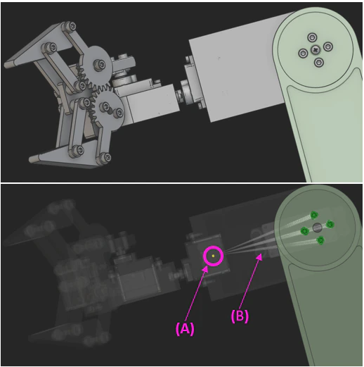
Rigid Connector Block
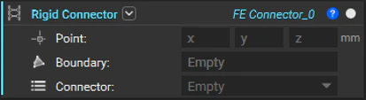
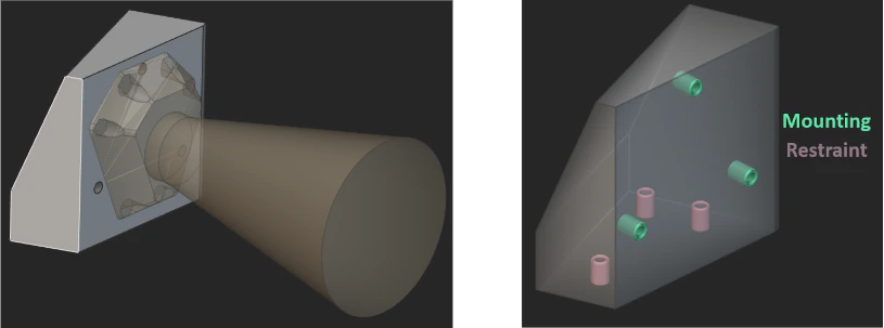
- Point: This is the location where the block will create a remote point. This is typically at the center of mass of the component being represented. To learn more about the attributes that can be applied to the point, please refer to the Point Attribute section in the Documentation.
- Boundary: This defines the boundaries (typically nodes on a surface) that will be connected to the point with rigid elements.
- Connector: This defines the behavior of the nodes on the boundary linked to the motion of the point and has 2 options:
-
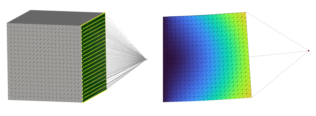
Rigid: The rigid option constrains the nodes on the boundary to move with the point. It prevents any relative motion between the nodes on the boundary and behaves like a rigid entity. This is popularly known as the RBE2 connector that connects an independent node (green) to a set of dependent nodes (yellow).
-
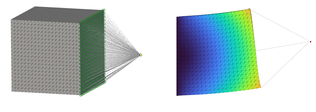
Flexible: This flexible option links the motion of the point to the nodes on the boundary and enables relative motion between these nodes. This distributes the mass between the nodes on the boundary and avoids locally stiffening the model (unlike the Rigid connector). This is popularly known as the RBE3 connector that connects a dependent node (yellow) to a set of independent nodes (green).
-
Rigid: The rigid option constrains the nodes on the boundary to move with the point. It prevents any relative motion between the nodes on the boundary and behaves like a rigid entity. This is popularly known as the RBE2 connector that connects an independent node (green) to a set of dependent nodes (yellow).
Example 1 — Modal Analysis and Optimization of a Camera Bracket
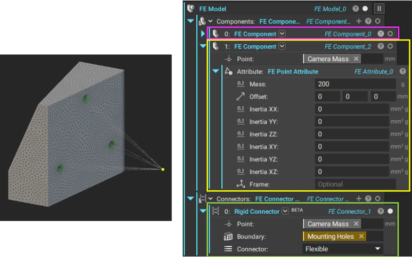
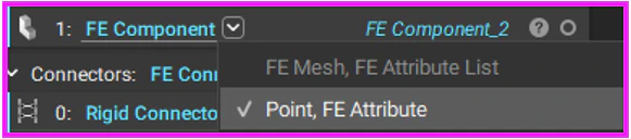
- Add a second FE Component to the FE Model. Use the second overload of the FE Component that takes a Point and an FE Attribute.
- In the Point input, specify the x, y, z location of the camera’s center of mass. In the attached example, this point is specified as a variable that contains the camera’s center of mass property.
- To the FE Attribute input, add an FE Point Attribute and input the mass properties of the camera. In the attached example, a mass of 200 g was specified in this block.
- In the Connectors input of the FE Model, add the Rigid Connector block.
- Enter the coordinates of the point representing the camera’s center of mass. Here, the center of mass variable was used to specify this input just like the FE Component block.
- Define the Boundary that the remote mass is connected to.
- Finally specify the connector type. In this example, the Flexible (RBE3) connector was used.
| Design 1 | Design 2 |
|---|---|
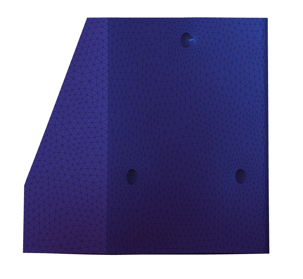 | 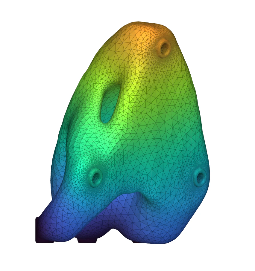 |
| 480 g | 178 g |
| 922 Hz | 635 Hz |
Example File
Download Example: Rigid Connector ExampleFE Point, Boundary, FE Coupling Enum
Defines a rigid element connector between a Point and Boundary. The connector may either be Flexible (RBE3) or Rigid (RBE2).Inputs
Outputs
| Type |
|---|
| Connector |
FE Point, Boundary, FE Coupling Enum
Defines a rigid element connector between a Point and FE Boundary. The connector may either be Flexible (RBE3) or Rigid (RBE2).Inputs
| Name | Type | Description |
|---|---|---|
| Fe point | FE Point | Point to create the connector from. |
| Boundary | CAD Face List | The dependent FE boundary. |
| Connector | FE Coupling Enum | Option to create either a flexible (RBE3) or rigid (RBE2) connector. |
Outputs
| Type |
|---|
| Connector |