Boundary, Boundary, Bool, Scalar
CAD Face, CAD Face, Bool, Scalar
About this Block
What it does: Connects two different Domains within the same Simulation Model. A boundary is chosen on each Domain and tied together with a tolerance. Common uses:- Connecting Domains in Simulation Model.
- Two unique boundary selection blocks choose the regions to be tied together. Depending on the choice of independent boundary entities, the following formulations are used:
- If faces are selected as independent boundary entities, each dependent node is tied with the closest face on the independent boundary. Shape function values of the face entity (at the dependent node location) are then used to generate tie constraint equations for the node-face pair.
- If nodes are selected as independent boundary entities, each dependent node is tied with the closest independent node (within the given tolerance).
- Tie constraints don’t support edges as the independent boundary.
- If the tolerance is too low to find any independent entities for at least one dependent node, an error will occur. You can fix this error by increasing the tolerance or editing the boundary.
- The Rotation checkbox toggles the option to tie rotational degrees of freedom.
Example File
Download Example: Tie Constraint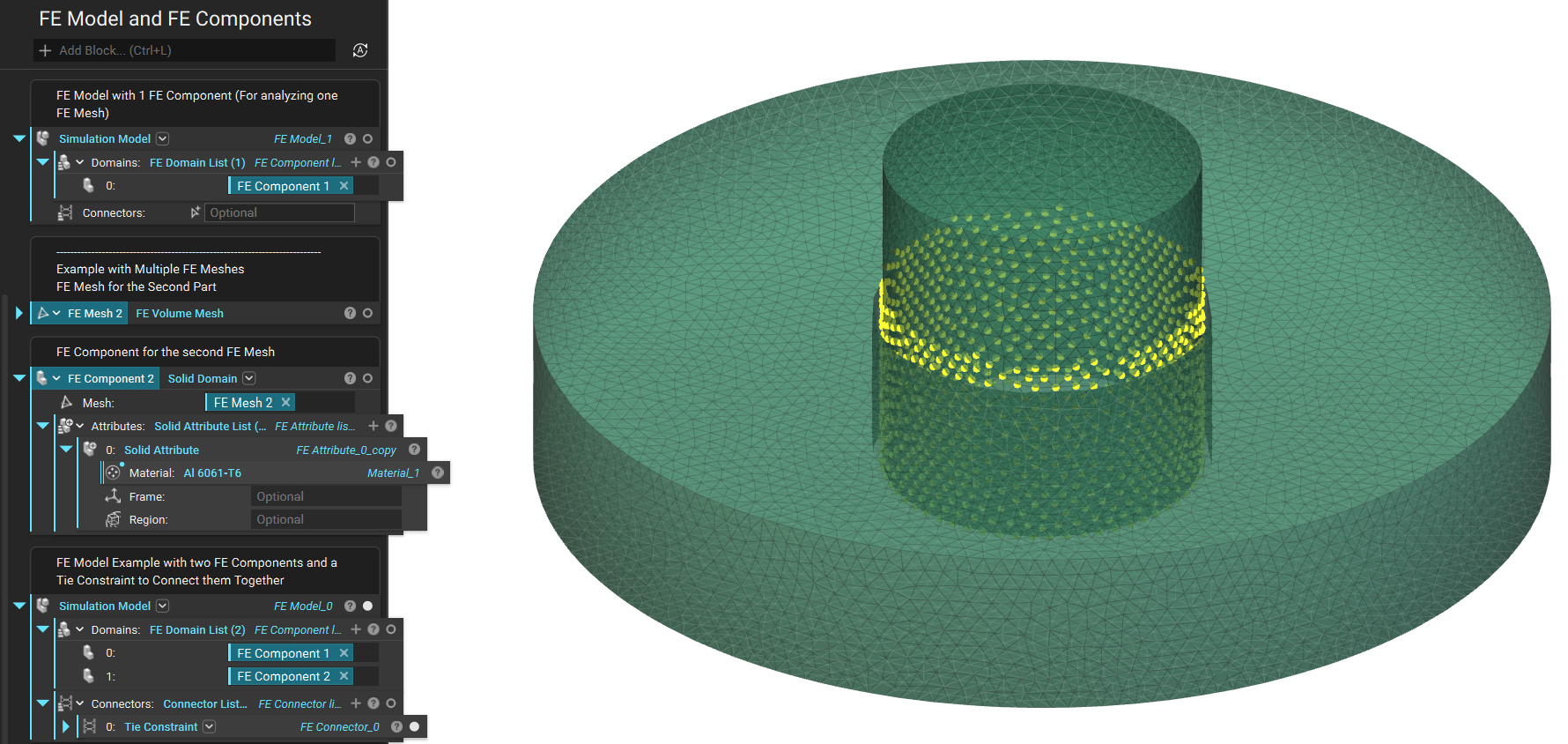
Boundary, Boundary, Bool, Scalar
Define a tie constraint between two boundary regions so that there is no relative motion between them for structural analysis and no temperature difference between them for thermal analysis. For each selected independent entity, the function looks for the dependent entity and checks if it lies within the radius distance of the independent entity. If no entities are found within the defined radius, the tie constraint will indicate an error.Inputs
| Name | Type | Description |
|---|---|---|
| Independent | Boundary | The independent boundary. |
| Dependent | Boundary | The dependent boundary. |
| Rotation | Bool | Option to tie rotational degrees of freedom. |
| Radius | Scalar | Positional tolerance for dependent boundary relative to the independent boundary. Nodes in the dependent boundary beyond this tolerance will not be constrained to the independent boundary. |
Outputs
| Type |
|---|
| Connector |
CAD Face, CAD Face, Bool, Scalar
Define a tie constraint between two boundary regions so that there is no relative motion between them. For each selected independent entity, the function looks for the dependent entity and checks if it lies within the radius distance of the independent entity. If no entities are found within the defined radius, the tie constraint will indicate an error.Inputs
| Name | Type | Description |
|---|---|---|
| Independent | CAD Face | The CAD face on the independent boundary. |
| Dependent | CAD Face | The CAD face on the dependent boundary. |
| Rotation | Bool | Option to tie rotational degrees of freedom. |
| Radius | Scalar | Positional tolerance for dependent boundary relative to the independent boundary. Nodes in the dependent boundary beyond this tolerance will not be constrained to the independent boundary. |
Outputs
| Type |
|---|
| Connector |