Objective:
Learn how to slice an implicit body into an image stack for additive manufacturing printers that accept images.Applies to:
- Additive Manufacturing
- Slices for Open DLP and Binderjet systems
Procedure:
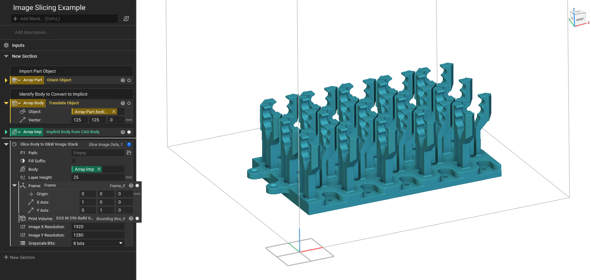
1. Prepare the part- Convert the part into an Implicit body
- If you are printing from an EOS M or Renishaw AM machine, you can choose from built-in Build Volume blocks.
- If your machine isn’t one of these, create your build volume with a Bounding Box block
- Use the Translate Object block to move the part into the Build Volume
- You may need to orient it or create support structures for an optimal build
- Add a Slice Body to B&W Image Stack block
- Path: Choose the destination to save the slices
- Fill Suffix:
- Toggled On: Names the files: “slice_001”, where the number of 0’s before the slice number is determined by the total number of slices.
- Toggled Off: The files are named “slice_1”, with no 0’s.
- Body: Insert the Implicit Body you want to slice.
- Layer Height: Define the spacing between the layers. You may need to check the printer settings for the appropriate range of heights.
- Frame: This is the coordinate system for the build plate. It is auto-populated but may need to be edited depending on the printer settings.
- Print Volume: Insert the Bounding Box or Build Volume from Step 2.
- The resolution is the number of pixels in the X and Y directions. This value may change depending on your printer and desired resolution. The maximum image resolution supported is 1 billion pixels.
- Image X resolution: 1920
- Image Y resolution: 1280
- Greyscale bits: 8 bits
 After all the inputs are filled, the block saves the resulting .png file format image stack in the zip folder defined earlier.
 And that’s it! You’ve successfully learned how to generate a B&W Image stack for manufacturing.
Are you still having issues? Contact the support team, and we’ll be happy to help!
And that’s it! You’ve successfully learned how to generate a B&W Image stack for manufacturing.
Are you still having issues? Contact the support team, and we’ll be happy to help!