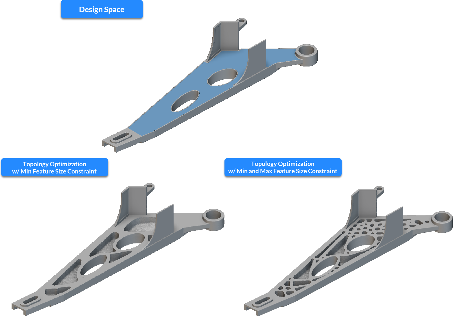
About this Block
The Min Feature Size Constraint block can be used as a constraint in the Topology Optimization block to maintain the feature sizes of the optimized design space above a user-defined value. This block is typically used to correct feature disconnections in the optimization result and to enforce a minimum feature size limit to the design space based on requirements from a manufacturing process.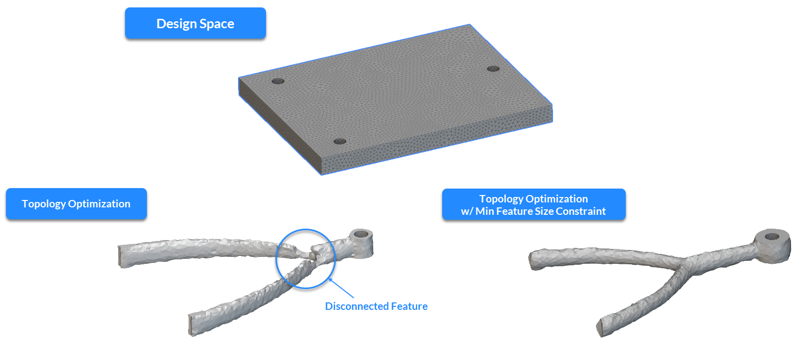 Like any Topology Optimization constraint, this block can be added to an Optimization Constraint List to enforce the desired feature size specification on the design space. While using the Min Feature Size Constraint block, there are a few factors to consider to ensure success while using this constraint that have been described in the following sections.
 Symmetry
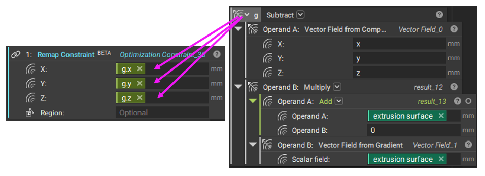
The Min Feature Size Constraint block can be used combined with a symmetry constraint to ensure a symmetric result about a plane (or a list of orthogonal planes) in the Topology Optimization block. It is recommended that the Remap Constraint block is used to apply the symmetry restriction instead of the Planar Symmetry Constraint block for the following reasons :
Symmetry
The Min Feature Size Constraint block can be used combined with a symmetry constraint to ensure a symmetric result about a plane (or a list of orthogonal planes) in the Topology Optimization block. It is recommended that the Remap Constraint block is used to apply the symmetry restriction instead of the Planar Symmetry Constraint block for the following reasons :
- The Remap Constraint is mesh-independent so that users can apply this constraint to non-symmetric meshes
- The optimization algorithm incorporates geometric constraints such as remap, symmetry, and extrusion as design filters. Unlike most filters, the Remap Constraint is applied as the final step in the filtering sequence. This prevents the amplification of any discrepancies through these projection filters used for the Min Feature Size Constraint, resulting in more accurate results
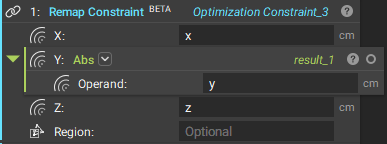 In the above image, the Remap Constraint inputs enforce symmetry about the XZ-plane. For more information, please refer to the support article on the topic. This recommendation applies to the Max Feature Size Constraint as well.
 While using the Min Feature Size Constraint or the Max Feature Size Constraint, it is recommended that the mesh edge length is at least 1/3rd the size of the desired feature size specification. In case this condition is not met, users are notified through a warning message in the log panel as indicated in the above image.
Iterations for constraint convergence
While using the Min Feature Size Constraint or the Max Feature Size Constraint, it is recommended that the mesh edge length is at least 1/3rd the size of the desired feature size specification. In case this condition is not met, users are notified through a warning message in the log panel as indicated in the above image.
Iterations for constraint convergence
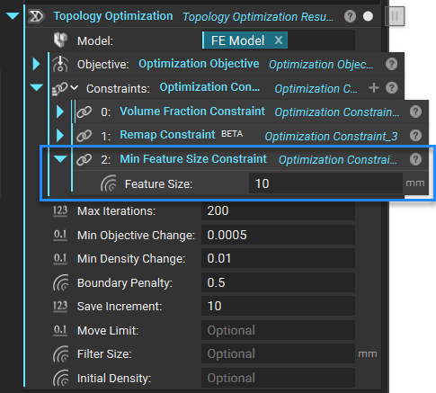
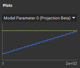 Setting the Max Iterations to a value that ensures the blue line meets the yellow dotted line is recommended. This is typically achieved at iterations greater than the default of 200 iterations in the block. It is recommended to set this parameter to at least 250 iterations when using the Feature Size Constraints.
Like all other optimization objectives and constraints, the progress of the Min Feature Size Constraint can be tracked from the Display tab in the Right Panel in the Topology Optimization block. The Min/Max Projection Beta tracks our main constraint filter parameter, updated throughout the optimization to not overconstrain the optimization right from the start.
Extrusion with the Remap Constraint
Setting the Max Iterations to a value that ensures the blue line meets the yellow dotted line is recommended. This is typically achieved at iterations greater than the default of 200 iterations in the block. It is recommended to set this parameter to at least 250 iterations when using the Feature Size Constraints.
Like all other optimization objectives and constraints, the progress of the Min Feature Size Constraint can be tracked from the Display tab in the Right Panel in the Topology Optimization block. The Min/Max Projection Beta tracks our main constraint filter parameter, updated throughout the optimization to not overconstrain the optimization right from the start.
Extrusion with the Remap Constraint
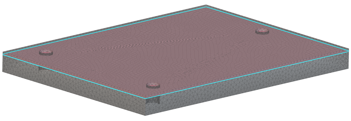
 A popular application of the Remap Constraint is to generate extrudable shapes in a user-defined direction (or multiple directions). This technique is described in detail in this support article in the Remap Constraint for Extrusion and Remap Constraint for Localized Ribbing section. When using the generalized form of the extrusion constraint (as indicated in the above image) with the Min Feature Size Constraint, it is recommended to embed the extrusion surface at least one element (element edge length) deep inside the design space (pictured below). The Min Feature Size Constraint tends to smoothen or “round” the design space at the boundaries. Suppose the surface used as reference is on the boundary, the final shape may present large transition areas between void and solid material or be incorrectly formed (with disconnections or thin connections). This recommendation also applies to scenarios where the Boundary Penalty input in Topology Optimization is set to any value besides 0.0.
 Passive Regions
 When defining a Passive Region Constraint in a Topology Optimization with the Min Feature Size Constraint, limiting the passive region thickness to ½ the feature size specification is recommended. Our solution already expands passive regions to achieve the defined minimum feature size. Because of that, when defining thick passive regions, the final solutions might present unexpected oversized regions. When this undesired situation happens with the Max Feature Size Constraint (using similar feature size inputs), it might lead to convergence problems since the bulged passive region may not respect the chosen feature size.
Domain Size
When defining a Passive Region Constraint in a Topology Optimization with the Min Feature Size Constraint, limiting the passive region thickness to ½ the feature size specification is recommended. Our solution already expands passive regions to achieve the defined minimum feature size. Because of that, when defining thick passive regions, the final solutions might present unexpected oversized regions. When this undesired situation happens with the Max Feature Size Constraint (using similar feature size inputs), it might lead to convergence problems since the bulged passive region may not respect the chosen feature size.
Domain Size
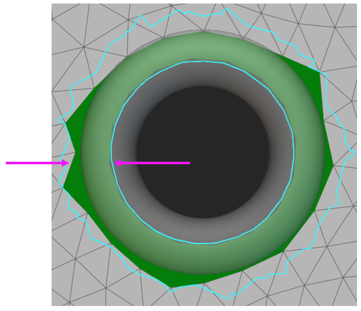
 If the feature size input in the Min Feature Size Constraint exceeds the domain size, the Topology Optimization may not yield satisfactory results. For instance, when optimizing the domain described in the above image, the feature size input should be less than the thickness of the domain (shown by the pink arrows).
Example Files
Download Examples: Simple Bracket Example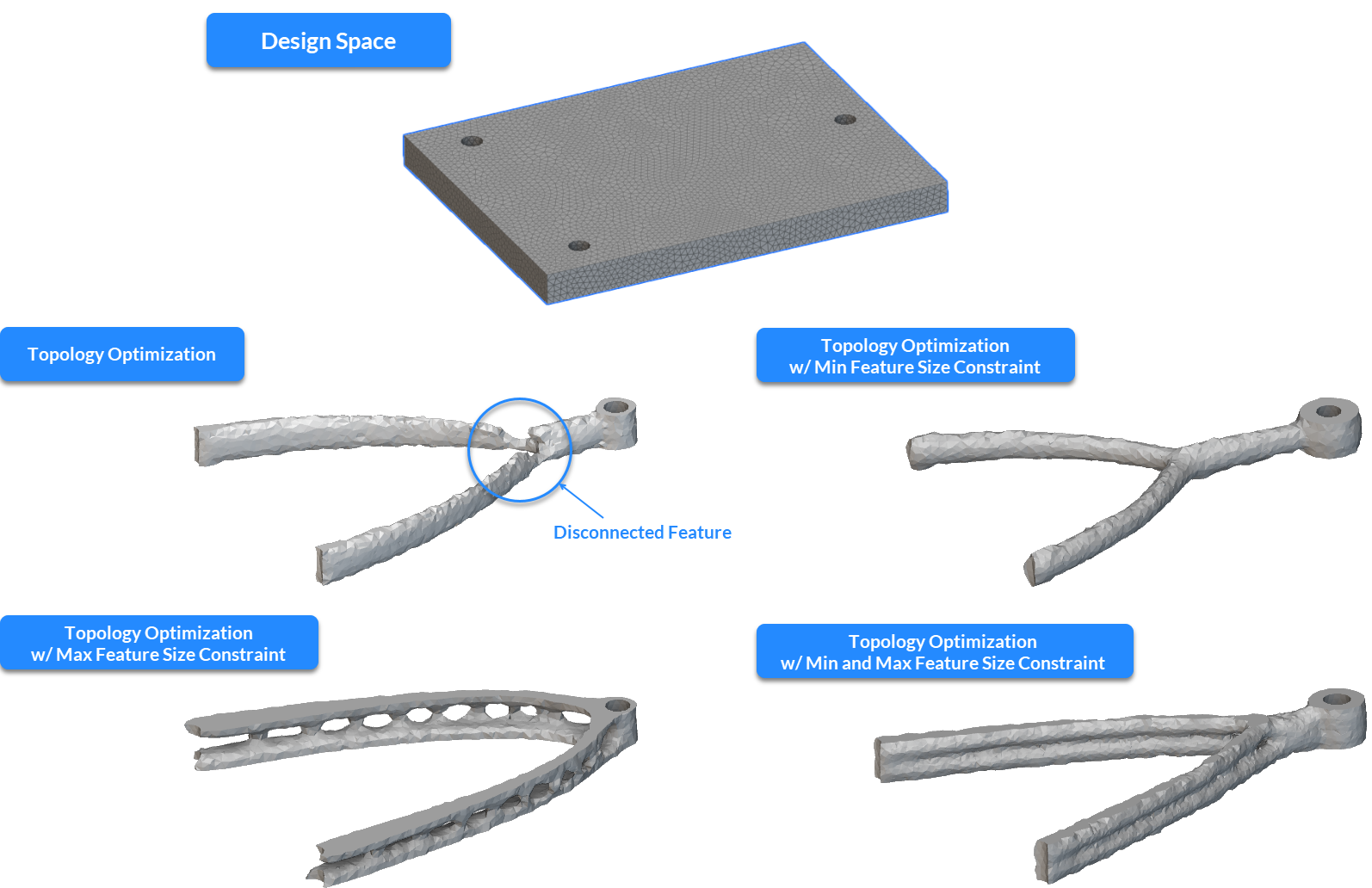 Swing Arm Extrusion
Define a constraint on the minimum feature size.
Inputs
| Name | Type | Description |
|---|---|---|
| Feature size | Scalar Field | The desired minimum length of any feature in the final design. This means that a sphere with a diameter specified by this input should fit inside any part of the final design. |