CAD Face, CAD Face, Vector, Bool
CAD Face, CAD Face, Vector, Bool, 1.1.0
CAD Face, CAD Face, Vector, Bool, 1.2.0
CAD Face, UV Position Enum, Bool, CAD Face, UV Position Enum, Bool, Vector, Bool
CAD Face, UV Position Enum, Bool, CAD Face, UV Position Enum, Bool, Vector, Bool, 1.1.0
CAD Face, UV Position Enum, Bool, CAD Face, UV Position Enum, Bool, Vector, Bool, 1.2.0
About this Block
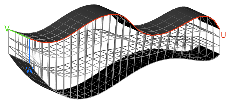
What it does: Constructs a Cell Map between two CAD Faces. The UVW count input specifies the number of cells in the three coordinate directions. This map serves as a layout for the lattice Unit Cells. Common uses:- Used as an input for the Periodic Lattice block.
- The UVW count input follows the UVW parameterization of the CAD Face. Once the block has run, UWV guides will appear on the Cell Map allowing you to visualize the CAD Face’s parameterization.
- If you’re unsure of what U, V, and W represent on your particular CAD Face, try inputting sample values so that the block runs. Then the UVW guides will appear.
- By default, this block tries to automatically pick the parameterizations of the input CAD Faces to achieve the best Cell Map between them. An overload is available to choose the input CAD Faces’ parameterizations manually.
- By default, the Cell Map contains straight edges only. Uncheck the Linear input for edges that curve more conformally to the CAD Faces.
- If the input CAD Face has an edge that degenerates to a point, then cells incident on that edge will be degenerate. Degenerate cells may be removed with the Trim Cell Map block if desired.
CAD Face, CAD Face, Vector, Bool
Constructs volumetric lattice cells between two CAD faces.Inputs
| Name | Type | Description |
|---|---|---|
| First face | CAD Face | First CAD surface to apply the cell map. |
| Second face | CAD Face | Second CAD surface to apply the cell map. |
| Uvw count | Vector | Number of cells in three directions. |
| Linear | Bool | Option to create a linear or curved cell map. As a general rule, check this option if your CAD faces are curved so that the Cell Map conforms more closely to the faces, although this will vary depending on the application. |
Outputs
| Type |
|---|
| Cell Map |
CAD Face, CAD Face, Vector, Bool, 1.1.0
Constructs volumetric lattice cells between two CAD faces.Inputs
| Name | Type | Description |
|---|---|---|
| First face | CAD Face | First CAD surface to apply the cell map. |
| Second face | CAD Face | Second CAD surface to apply the cell map. |
| Uvw count | Vector | Number of cells in three directions. |
| Linear | Bool | Option to create a linear or curved cell map. As a general rule, check this option if your CAD faces are curved so that the Cell Map conforms more closely to the faces, although this will vary depending on the application. |
Outputs
| Type |
|---|
| Cell Map |
CAD Face, CAD Face, Vector, Bool, 1.2.0
Constructs volumetric lattice cells between two CAD faces.Inputs
| Name | Type | Description |
|---|---|---|
| First face | CAD Face | First CAD surface to apply the cell map. |
| Second face | CAD Face | Second CAD surface to apply the cell map. |
| Uvw count | Vector | Number of cells in three directions. |
| Linear | Bool | Option to create a linear or curved cell map. As a general rule, check this option if your CAD faces are curved so that the Cell Map conforms more closely to the faces, although this will vary depending on the application. |
Outputs
| Type |
|---|
| Cell Map |
CAD Face, UV Position Enum, Bool, CAD Face, UV Position Enum, Bool, Vector, Bool
Constructs a Cell Map between two CAD faces.Inputs
| Name | Type | Description |
|---|---|---|
| First face | CAD Face | The first CAD surface to apply the cell map. |
| First uv origin | UV Position Enum | Corner parameter to set as origin for UV space of first face. |
| Flip first uv | Bool | Swap the direction of U and V for first face. |
| Second face | CAD Face | Second CAD surface to apply the cell map. |
| Second uv origin | UV Position Enum | Corner parameter to set as origin for UV space of second face. |
| Flip second uv | Bool | Swap the direction of U and V for second face. |
| Uvw count | Vector | Number of cells in the U, V and W directions. |
| Linear | Bool | Option to create a linear or curved cell map. As a general rule, check this option if your CAD faces are curved so that the Cell Map conforms more closely to the faces, although this will vary depending on the application. |
Outputs
| Type |
|---|
| Cell Map |
CAD Face, UV Position Enum, Bool, CAD Face, UV Position Enum, Bool, Vector, Bool, 1.1.0
Constructs a Cell Map between two CAD faces.Inputs
| Name | Type | Description |
|---|---|---|
| First face | CAD Face | The first CAD surface to apply the cell map. |
| First uv origin | UV Position Enum | Corner parameter to set as origin for UV space of first face. |
| Flip first uv | Bool | Swap the direction of U and V for first face. |
| Second face | CAD Face | Second CAD surface to apply the cell map. |
| Second uv origin | UV Position Enum | Corner parameter to set as origin for UV space of second face. |
| Flip second uv | Bool | Swap the direction of U and V for second face. |
| Uvw count | Vector | Number of cells in the U, V and W directions. |
| Linear | Bool | Option to create a linear or curved cell map. As a general rule, check this option if your CAD faces are curved so that the Cell Map conforms more closely to the faces, although this will vary depending on the application. |
Outputs
| Type |
|---|
| Cell Map |
CAD Face, UV Position Enum, Bool, CAD Face, UV Position Enum, Bool, Vector, Bool, 1.2.0
Constructs a Cell Map between two CAD faces.Inputs
| Name | Type | Description |
|---|---|---|
| First face | CAD Face | The first CAD surface to apply the cell map. |
| First uv origin | UV Position Enum | Corner parameter to set as origin for UV space of first face. |
| Flip first uv | Bool | Swap the direction of U and V for first face. |
| Second face | CAD Face | Second CAD surface to apply the cell map. |
| Second uv origin | UV Position Enum | Corner parameter to set as origin for UV space of second face. |
| Flip second uv | Bool | Swap the direction of U and V for second face. |
| Uvw count | Vector | Number of cells in the U, V and W directions. |
| Linear | Bool | Option to create a linear or curved cell map. As a general rule, check this option if your CAD faces are curved so that the Cell Map conforms more closely to the faces, although this will vary depending on the application. |
Outputs
| Type |
|---|
| Cell Map |