CAD Face, Vector, Scalar Field, Bool
CAD Face, Vector, Scalar Field, Bool, 1.1.0
CAD Face, Vector, Scalar Field, Bool, 1.2.0
About this Block
What it does: Constructs a Cell Map from a selected CAD Face. The UVW count input specifies the number of cells in the three coordinate directions. This map serves as a layout for the lattice Unit Cells. Common uses:- Used as an input for the Periodic Lattice block.
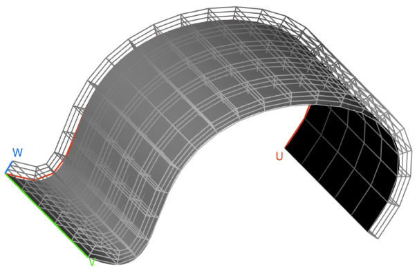
- The UVW count input follows the UVW parameterization of the CAD Face. Once the block has run, UWV guides will appear on the Cell Map allowing you to visualize the CAD Face’s parameterization.
- If you’re unsure of what U, V, and W represent on your particular CAD Face, try inputting sample values so that the block runs. Then the UVW guides will appear.
- Points in the Cell Map are generated as normal offsets of points on the input CAD Face.
- Self-intersections may occur in the Cell Map due to nearby surface points colliding while offsetting along their normals.
- By default, the Cell Map contains straight edges only. Uncheck the Linear input for edges that curve more conformally to the CAD Face.
- If the input CAD Face has an edge that degenerates to a point, then cells incident on that edge will be degenerate. Degenerate cells may be removed with the Trim Cell Map block if desired.
CAD Face, Vector, Scalar Field, Bool
Constructs a Cell Map from a CAD face.Inputs
| Name | Type | Description |
|---|---|---|
| Face | CAD Face | CAD surface on which to apply the Cell Map. |
| Uvw count | Vector | Number of cells in the U, V, and W directions. |
| Height | Scalar Field | Height of the Cell Map from the CAD face. |
| Linear | Bool | Option to create a linear or curved cell map. As a general rule, check this option if your CAD face is curved so that the Cell Map conforms more closely to the face, although this will vary depending on the application. |
Outputs
| Type |
|---|
| Cell Map |
CAD Face, Vector, Scalar Field, Bool, 1.1.0
Constructs a Cell Map from a CAD face.Inputs
| Name | Type | Description |
|---|---|---|
| Face | CAD Face | CAD surface on which to apply the Cell Map. |
| Uvw count | Vector | Number of cells in the U, V, and W directions. |
| Height | Scalar Field | Height of the Cell Map from the CAD face. |
| Linear | Bool | Option to create a linear or curved cell map. As a general rule, check this option if your CAD face is curved so that the Cell Map conforms more closely to the face, although this will vary depending on the application. |
Outputs
| Type |
|---|
| Cell Map |
CAD Face, Vector, Scalar Field, Bool, 1.2.0
Constructs a Cell Map from a CAD face.Inputs
| Name | Type | Description |
|---|---|---|
| Face | CAD Face | CAD surface on which to apply the Cell Map. |
| Uvw count | Vector | Number of cells in the U, V, and W directions. |
| Height | Scalar Field | Height of the Cell Map from the CAD face. |
| Linear | Bool | Option to create a linear or curved cell map. As a general rule, check this option if your CAD face is curved so that the Cell Map conforms more closely to the face, although this will vary depending on the application. |
Outputs
| Type |
|---|
| Cell Map |