About this Block
The Parametric Shell Domain block creates a Parametric FE Domain, which has been parameterized for variable shell thickness. The block uses a FE Volume Mesh as an input Mesh to define the design space. After field optimization, the optimized values for the shell thickness will apply to the design space. Common uses: This block is an input to the Parametric FE Model block. Once the Parametric Lattice Domain is generated, a HUD appears in the Viewport with several options for visualizing the results.- Implicit View - allows you to view the resulting geometry.
- Property Fields - allows a user to view the mechanical properties of the structure across the design space before performing field optimization.
- State Fields - allows a user to view values of the design parameters across the design space before performing the field optimization.
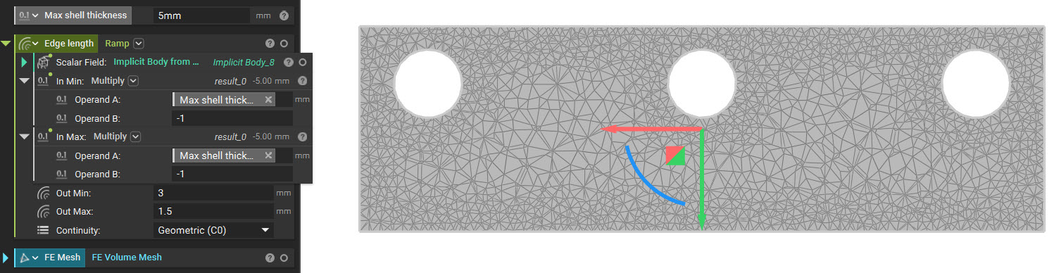
- Determining the proper mesh size can be difficult for the FE mesh provided to the Parametric Shell Domain.
- The input mesh must be very fine from the surface through the maximum shell thickness.
- However, to increase the speed/efficiency of the optimization algorithm, elements outside of the “shell boundary” should be much larger.
- The goal is for the total possible design region to contain as many elements as possible (giving up time for accuracy) and for all other areas to contain fewer elements.
- As such, you should use a Ramp block in the Edge Length input to generate the FE Mesh. An example of meshing for shell optimization is below:
- Taking advantage of the SDF of an implicit, we can ramp our mesh edge length using our ramp function. Some hints for appropriate inputs are below:
- Scalar Field: Implicit body which we are meshing. The implicit body will allow us to use the signed distance field of the implicit in driving our mesh size.
- In Min: Maximum shell thickness multiplied by -1. This input will create a divider between the maximum design space of the shell optimization and the void on the inside.
- In Max: Maximum shell thickness multiplied by -1. Having the same input as “In Min,” we can set up the field as a step function.
- Out Min: Mesh size of shell design space (should be smaller than “Out Max”). The edge size should capture all the detail of the object and be suitable for running simulation.
- Out Max: Mesh size of the inner void (should be more significant than “Out Min”).
- Adjust the Initial Shell Thickness to view the geometry generated for the upper/lower bounds to ensure printability before running a field optimization.
Example File
Download Example: Parametric Shell Domain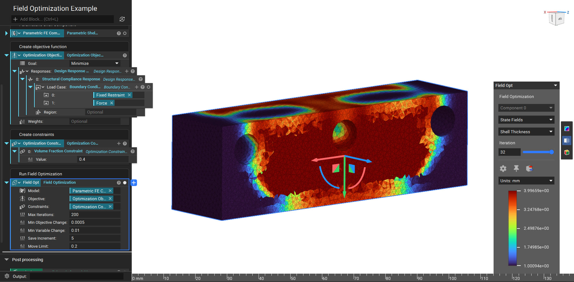
Create a Parametric FE Domain for a variable shell structure with the following design parameters: shell thickness (inward direction).
Inputs
| Name | Type | Description |
|---|---|---|
| Mesh | FE Mesh | The finite element mesh that defines the design space. |
| Material | Isotropic Material | The material definition of the shell domain. |
| Min shell thickness | Scalar Field | The minimum allowable thickness for the shell. |
| Max shell thickness | Scalar Field | The maximum allowable thickness for the shell. |
| Initial shell thickness | Scalar Field | The initial shell thickness. This defines the starting point of the optimization. Values exceeding the min/max bounds will be clamped. |
| Filter size | Scalar Field | A length measure used to control the smoothness of the design parameter field. A lower bound of 0 will be enforced. If not specified, a default will be estimated based on the model size. |