Objective:
Learn how to create a knurled texture.Applies to:
- Texturing
- Industrial design
Procedure:
1. Set up the faces and bodies.- Start with any imported CAD Body.
- Select the faces for knurling and create a CAD Face List Variable.
- Convert the CAD bodies (main bodies and knurl body) to Implicit bodies by Implicit Body from CAD Body to be used in the last two steps.
 2. Create the lattice knurled pattern.
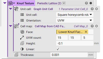
- Add a Periodic Lattice block.
- Unit cell: Graph Unit Cell.
- Unit cell: Square honeycomb rotated.
- Orientation: UVW.
- Cell map: Cell Map on CAD Face.
- Face: Lower Knurl Faces (variable created from the above step).
- UVW count: 15, 15, 5.
- Height: -0.1 mm (a negative offset distance will move inward, while a positive offset distance will move outward)
- Thickness: 0.001 mm.
- Unit cell: Graph Unit Cell.
 3. Converting List to a single body.
- Boolean Union the Thicken Body to convert from a list to a single body.
- Blend Radius: 0 mm.
- Drag and Drop the Implicit chip of Knurl Lattice (from the Conformal Lattice from CAD Face block).
- Boolean Subtract the thickened lattice from the knurl section. This will cut into the surface and create the knurling texture.
- Blend Type: Chamfered.
- Blend Radius: 0.125 mm.
- Primary Body: Implicit Knurl Body (from setting up the faces and bodies).
- Subtraction Body: Boolean Union (from creating the Knurl Pattern).
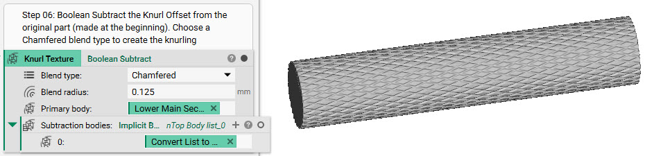 And that’s it! You’ve successfully created a knurled surface texture.
Are you still having issues? Contact the support team, and we’ll be happy to help!
And that’s it! You’ve successfully created a knurled surface texture.
Are you still having issues? Contact the support team, and we’ll be happy to help!