Objective
Use feature size constraints to ensure manufacturability and correct feature disconnections in Topology Optimization results.Applies to:
Topology Optimization workflows.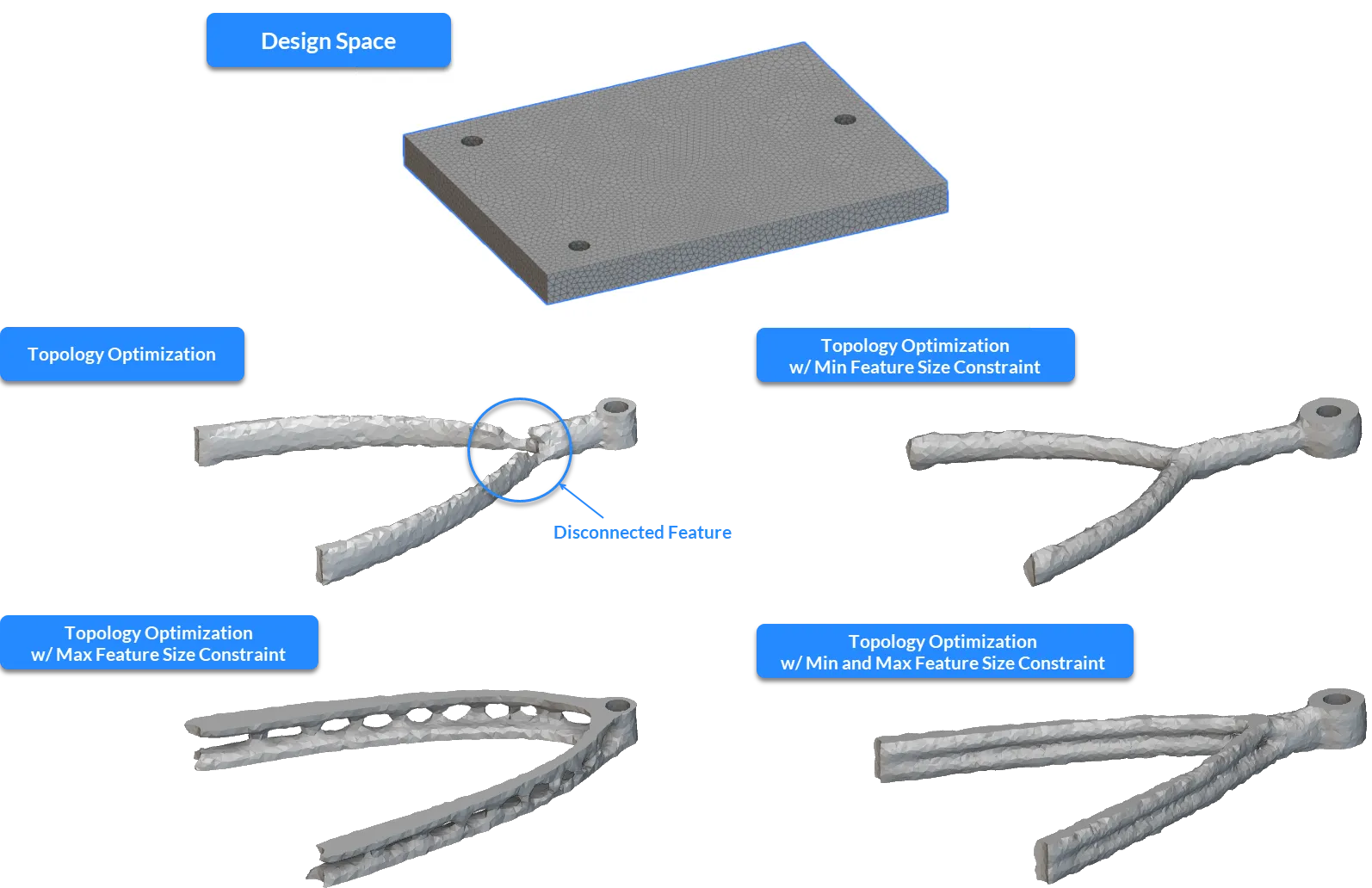 ## Procedure
1. Optimize Your Mesh Size
To accurately capture feature size constraints, your mesh must be sufficiently refined.- Ensure the element edge length of your FE mesh is at most 1/3 the size of your desired feature size specification.
2. Apply the Constraints
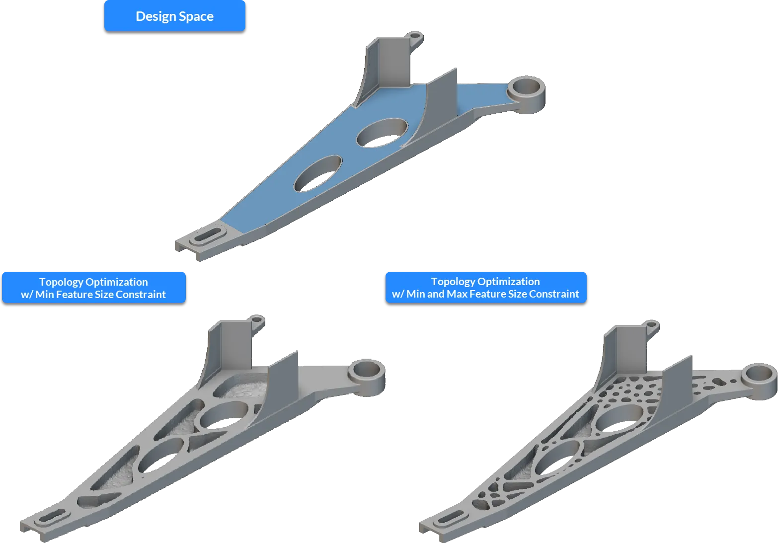
Add the Min Feature Size Constraint and/or Max Feature Size Constraint blocks to your Optimization Constraint List.- Min Feature Size: Prevents feature disconnections and enforces manufacturing limits.
- Max Feature Size: Prevents the design from becoming too bulky or violating space constraints.
- Domain Size: Ensure your feature size input is less than the total thickness of your design domain.
 ### 3. Configure other Constraints
For the most accurate results, use field-based constraints rather than traditional planar constraints.
### 3. Configure other Constraints
For the most accurate results, use field-based constraints rather than traditional planar constraints.
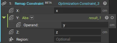
- Symmetry: Use the Remap Constraint block instead of the Planar Symmetry Constraint. The Remap Constraint is mesh-independent and acts as the final step in the filtering sequence, preventing discrepancies from being amplified.
 - Extrusion: If using a Remap Constraint for extrusion, embed the reference surface at least one element deep inside the design space to prevent disconnections at the boundaries.
- Passive Region: It is recommended to limit the passive region thickness to half the feature size specification. Our solution already expands passive regions to achieve the defined minimum feature size. As a result, when defining thick passive regions, the final solutions may present unexpectedly oversized regions. When this undesired situation occurs with the Max Feature Size Constraint (using similar feature size inputs), it may lead to convergence problems, as the bulged passive region may not respect the chosen feature size.
 ### 4. Set Algorithmic Parameters
Feature size constraints require more iterations to converge than standard optimizations.
### 4. Set Algorithmic Parameters
Feature size constraints require more iterations to converge than standard optimizations.
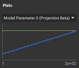
- Set the Max Iterations to at least 250 (the default is 200).
- The goal is to ensure the Min/Max Projection filter (blue line in the convergence plot) meets the target (yellow dotted line).
 ### 5. Monitor Convergence
Once the optimization begins, navigate to the Display tab in the Topology Optimization block.
### 5. Monitor Convergence
Once the optimization begins, navigate to the Display tab in the Topology Optimization block.
- Min/Max Projection: Tracks the primary constraint filter.
- Plot: For the Max Feature Size Constraint, the value should always be below 1 (the yellow dotted line) to remain within the defined input.
Example Files