Objective:
nTop offers some manufacturing constraints, including the Overhang Constraint for additive manufacturing. This article teaches you how to use the constraint and shows the differences between a constrained and unconstrained example.
Applies to:
- Optimization
- Additive Manufacturing
Procedure:
- Add an Overhang Constraint block
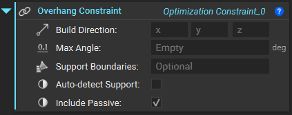
- Define the Build directionas a vector. This corresponds to the direction of manufacturing. If your part is already oriented on the X-Y plane, then this will typically be the Z+ direction, corresponding to a vector of <0,0,1>.
- Specify the Max Angle, the maximum allowable overhang angle that the manufacturing process allows.
- Specify the Support Boundaries (optional), which are the regions you want to allow support structures to be applied to. Use the FE Boundary by Body, FE Boundary by Flood Fill, or FE Face Boundary. The support boundaries need to use Face selection, so please select that in the boundary block.
- Check the Auto-Detect Support if you would like to auto-detect the faces of the design space that can provide support for the given print direction and overhang angle.
- Check the Include Passive if you would like to include the passive region in the overhang region optimization. If not selected, the passive regions will be ignored.
- The Overhang Constraint can now be input into the Constraints list of an existing Topology Optimization.
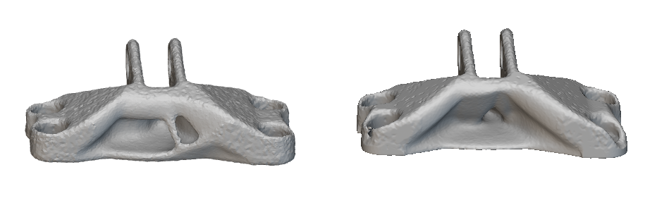 Unconstrained results on the left and results with an overhang constraint of 45 degrees on the right.
And that’s it! You’ve successfully used the overhang constraint for Topology Optimization.
Are you still having issues? Contact the support team, and we’ll be happy to help!
Unconstrained results on the left and results with an overhang constraint of 45 degrees on the right.
And that’s it! You’ve successfully used the overhang constraint for Topology Optimization.
Are you still having issues? Contact the support team, and we’ll be happy to help!