Objective:
Learn how to run a topology optimization.Procedure:
What is Topology Optimization?
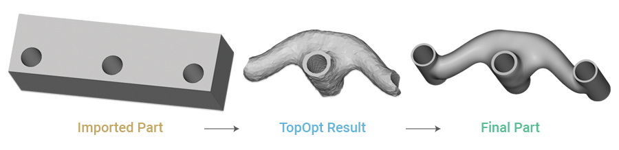
Topology Optimization (TopOpt) is a numerical design operation that determines the optimal shape of a part based on a set of performance objectives and constraints. This lets you generate optimized, lightweight designs that meet specific engineering requirements. This guide walks through the complete workflow for designing a lightweight bracket with minimum structural compliance (maximizing stiffness)What You’ll Learn
- How do you prepare a CAD part and FE mesh for TopOpt?
- How to set up a simulation model with boundary conditions.
- How to define TopOpt objectives and constraints.
- How to run the optimization and interpret the results.
- How do we post-process the results into a final part?
Step 1: Prepare the Design Space and Material
- Import your starting CAD part. In this example, we use a rectangular block with three holes.
- Create variables from the CAD geometry. This makes them easy to reference later.
- Design Space: The entire CAD Body.
- Restrained Faces: The faces of the two outer holes.
- Loaded Face: The face of the center hole.
- Interfaces: All three hole features will be kept in the final design.
- Define the material properties. For this bracket, we’ll use an Isotropic Elastic Property with a Young’s modulus of
2.1e+11 Paand a Poisson’s Ratio of0.33.
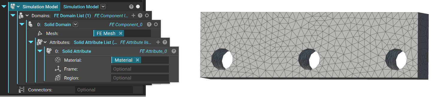
Step 2: Create the Simulation Model
Follow this article to create an FE Volume Mesh from the Design Space.- Create an FE Volume Mesh from the Design Space CAD part. An
3 mmedge length with a Geometric Order ofLinearis suitable for this example. - Create a Simulation Model using the FE Volume Mesh and the Material defined in the previous step.
Step 3: Define Boundary Conditions
Use this article for reference when creating Boundary Conditions. In this example, we want a Force acting on the middle face and a Displacement Restraint acting on the two outer faces. Displacement Restraint:- Add a Displacement Restraint block
- Input the Restrained Facesas the Boundary input
- Add a Force block
- Input the Loaded Face as the Boundary input
- Set the Vector to (0, 1000, 0) N
Step 4: Set Up and Run the Topology Optimization
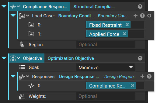
Now we can define the rules for the optimization.Define the Objective
The objective is what property, or ‘design response,’ we hope to minimize or maximize within our part. nTop supports several design responses, including structural compliance, volume fraction, displacement, and stress. Use the Optimization Objective block to specify the design response(s). In this example, the objective is to minimize structural compliance.- Add a Structural Compliance Response block
- Insert the Displacement Restraint and the Force block from the last step
- Add an Optimization Objective block
- Set the goal to Minimize
- Insert the Structural Compliance Response into the Design Response List
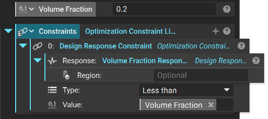
Define the Constraint
Topology optimization also requires the user to provide constraints. An under-constrained TopOpt process will simply fill in or remove all volume from the design region because those results lead to minimization or maximization of the design response. Therefore, TopOpt procedures must be properly constrained in order to achieve meaningful results. The most commonly used constraint simply applies a minimum or maximum bound to a design response, such as compliance, volume fraction, displacement, or stress. This TopOpt example is constrained such that the volume fraction of the final part is less than 0.2. In other words, the resulting optimized part will have a targeted volume of 20% of the whole design space. Notice that the volume fraction cutoff in the Design Response Constraint block is made into a variable for easy adjustment.- Add an Optimization Constraint List block
- Insert a Design Response Constraint block
- Insert a Volume Fraction Response block into the Response input
- Set the value to 0.2
- Optional: Right-click on the Value input to create a variable to quickly change the Volume Fraction
- Insert a Design Response Constraint block
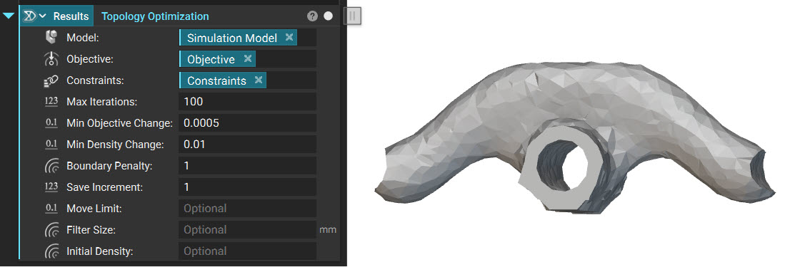
Run the Optimization
- Add a Topology Optimization block,
- Insert the Simulation Model, Objective, and Constraints
 The TopOpt process works by assigning a value between 0 and 1 to all of the mesh elements. Higher values are assigned to elements that most effectively contribute to the optimization objective. These values are referred to as the TopOpt density.
For example, an element in the bottom corner of the design space, far away from the applied load, is given a density value close to 0 because placing material here does not contribute to the goal of minimizing structural compliance. On the other hand, elements close to the loaded center hole are given a density value close to 1 because having material there is necessary to support the load.
The Thresholded Elements option in the TopOpt viewing window lets the user see what density values have been assigned to all elements in the design space. Use the Threshold slider to only view elements with a value higher than the specified threshold.
The TopOpt process works by assigning a value between 0 and 1 to all of the mesh elements. Higher values are assigned to elements that most effectively contribute to the optimization objective. These values are referred to as the TopOpt density.
For example, an element in the bottom corner of the design space, far away from the applied load, is given a density value close to 0 because placing material here does not contribute to the goal of minimizing structural compliance. On the other hand, elements close to the loaded center hole are given a density value close to 1 because having material there is necessary to support the load.
The Thresholded Elements option in the TopOpt viewing window lets the user see what density values have been assigned to all elements in the design space. Use the Threshold slider to only view elements with a value higher than the specified threshold.
 The Iso-contour view shows a single surface interpolated from all elements with TopOpt density values close to the specified threshold.
 The Iteration slider allows you to see the evolution of the TopOpt throughout the optimization iterations.
Step 5: Post-Process the Results into a Final Part
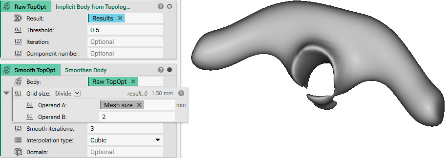
Once you have inspected your TopOpt results and found an acceptable threshold value, we can convert them into an Implicit Body. Convert to an Implicit Body:- Add an Implicit Body from Topology Optimization Results block
- Input the Topology Optimization block
- Set the Threshold value to 0.5 (it may be different depending on your preference)
- Add a Smoothen Body block.
- A good Grid Size for smoothing is half the FE mesh edge length. Use a Divide block with the mesh edge length (
3 mm) as Operand A and2as Operand B.
- A good Grid Size for smoothing is half the FE mesh edge length. Use a Divide block with the mesh edge length (
Consolidate the Part
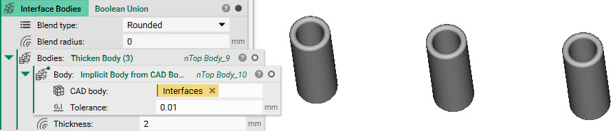
The topology-optimized volume is now ready to be recombined with the interfaces of the original CAD geometry. This step will look different depending on your part. If you are following along, do this:- Add an Implicit Body from CAD Body block
- Insert the Interfaces (all three CAD faces from Step 1)
- Add a Thicken Body block
- Insert the Implicit Body from CAD Body block
- Set the Thickness to 2 mm
- Add a Boolean Union block
- Delete the auto-generated list and input the Thicken Body block
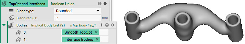
- Add a Boolean Union block
- Input the Smoothened TopOpt and the Interface Bodies
- Set the Blend radius to 2 mm (to keep the transitions between bodies congruent)
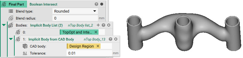
 Finally, use a Boolean Intersect to trim any excess material. Intersect the result from the previous step with an Implicit Body from CAD Body of the original Design Space.
- Add a Boolean Intersect block
- Input the TopOpt and Interfaces boolean union
- Input an Implicit Body from CAD Body block
- Input the Design Space
 And that’s it! You’ve successfully performed a Topology Optimization.
Are you still having issues? Contact the support team, and we’ll be happy to help!
And that’s it! You’ve successfully performed a Topology Optimization.
Are you still having issues? Contact the support team, and we’ll be happy to help!