- Set a planar path to define the duct centerline and flow direction.
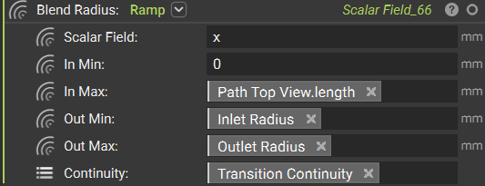
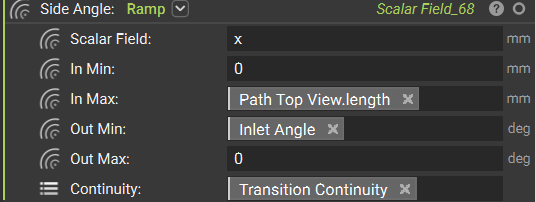
- Generate a ramped profile to control the cross-sectional shape transition.
- Make a planar duct along the profile using field-based operations.
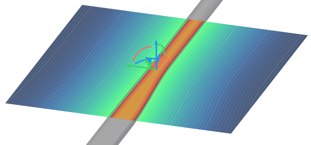
- Remap duct in the z direction to implement 3D spatial positioning.
1. Planar Profile
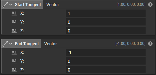
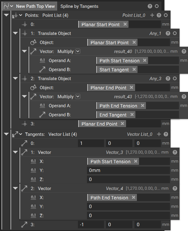
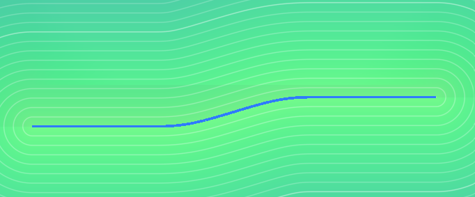
Set a planar path to define the duct centerline and flow direction. Ultimately, our ducting will exist in all 3 dimensions of our coordinate system. Let’s simplify this, beginning with only the x and y coordinates, and saving z for later. In this step, we will establish the path in the xy plane that one side of our ducting will follow. Again, we will begin by modeling the ducting unilaterally, then mirroring later on for simplicity. Some additional parameters we’ll use to control the path are- Butt Line Zero to establish the aircraft’s centerline symmetry plane.
- Path Start/End Tension to control how “stiff” the spline curve is at its endpoints
- Transition Continuity to set the mathematical smoothness level for all transitions in the workflow
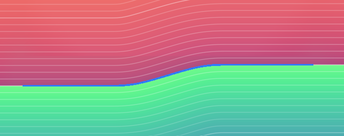
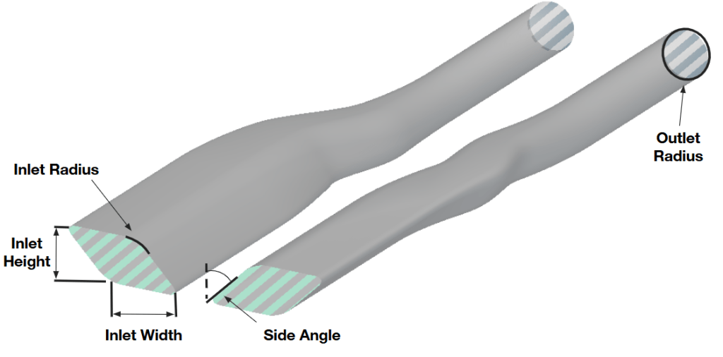
2. Ramped Profile
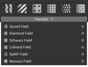
Generate a ramped profile to control the cross-sectional shape transition. Now, let’s generate a ramped parallelogram profile like the one that will form our duct cross-section. We’ll use a custom block to help simplify our overall workflow. Our goal in this step is to create a parametric shape that transitions smoothly from the inlet’s rectangular geometry to the outlet’s circular geometry along our spline path. You can take different approaches when creating your duct cross-section:- Simple geometric approach: Use basic rectangles or circles that change size along the path
- Parametric parallelogram approach: Create angled, blended shapes that optimize airflow characteristics
- Custom profile approach: Import or manually define complex cross-sectional shapes
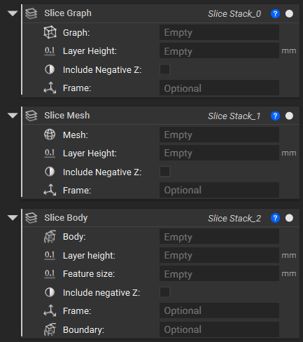
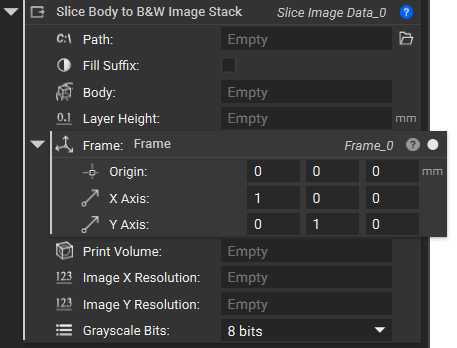
3. Planar Duct
Make a planar duct along the profile using field-based operations. Now let’s modify the geometry we created above to:- Follow our planar path
- Mirror the result to generate bilateral ducts
- Align with our inlet location (we’ll handle outlet alignment in the final step to compensate for any z-coordinate mismatches)
- x: Spline length field
- y: Distance to extrusion (the SDF representing distance from any point to the infinite extrusion of the profile)
- z: Negative z-coordinate
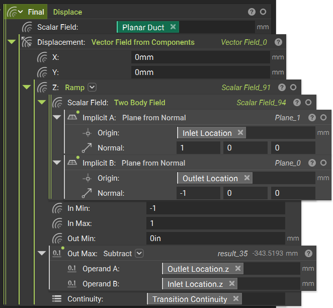
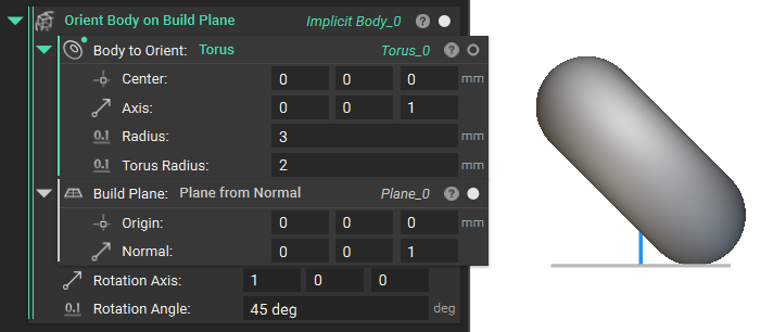
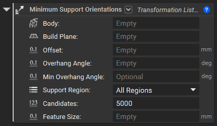
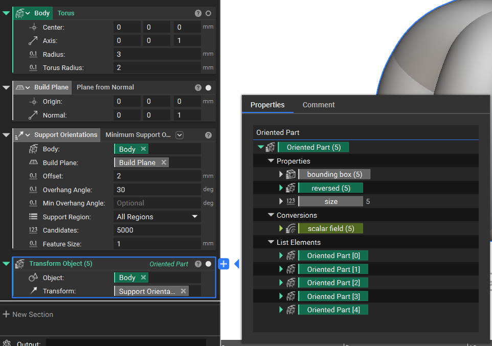
4. 3D Duct
Remap duct in the z direction to implement 3D spatial positioning. In these final steps, we’ll apply displacement fields in the z-direction to compensate for elevation differences between the inlet and outlet locations. To handle this vertical offset, we’ll use the Displace block. We can set the x and y displacements to zero, since we’ve already accounted for the top-view duct profile in our earlier sketching. To achieve a smooth z-direction transition we will:- Use the Two Body Field between planes positioned at the inlet and outlet locations
- Feed this field into a Ramp function
- Apply linear z-displacement from inlet to outlet elevation (this can be adjusted for non-linear displacement if preferred)