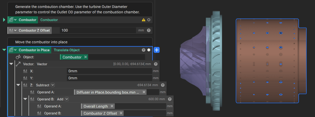
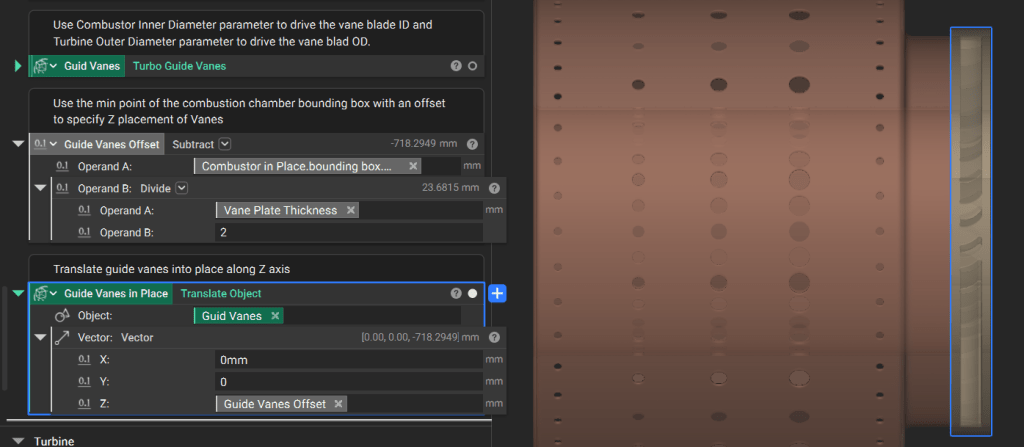
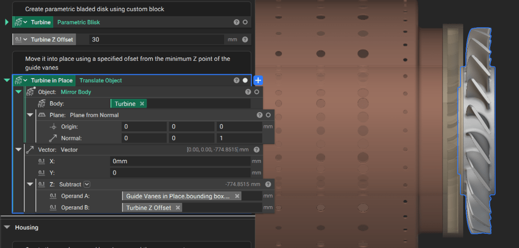
1. Move Components into Place
In a parametric assembly, component locations should reference a common origin or the dimensions of adjacent parts to ensure the model updates correctly when parameters change. Establish a Reference Point: The Impeller custom block generates the base of the impeller at the origin (0, 0, 0). All subsequent components use this point as their primary reference. Capture Tolerances: Use variables and basic math to define fits. For example, set the Impeller Max Radius as a variable and add a tolerance value to drive the Wedge Diffuser Inner Radius. Use the Translate Object block to position the Wedge Diffuser. Since the original block centers the diffuser on the origin, translate it along the Z-axis by half the base plate thickness plus an offset tolerance.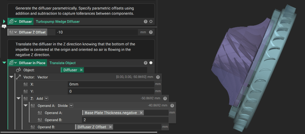
min Z point of the diffuser’s bounding box. Move it down by the overall length parameter plus a Z-offset.
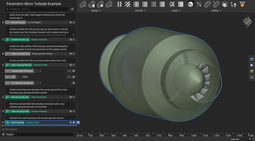
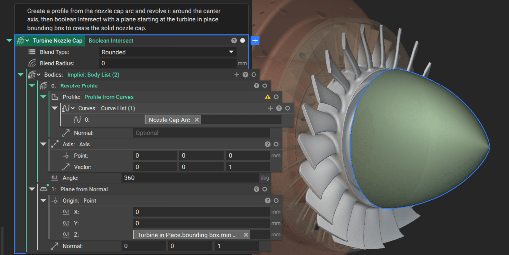
2. Generate the Nozzle Cap
The nozzle cap directs exhaust flow and is defined by the dimensions of the turbine wheel (Blisk). Define the Profile: Generate an arc for the nozzle cap side profile. Parametrize its points using themin Z point and inner diameter of the Blisk.
Modify the “pointiness” of the cap by changing the start tangent of the arc.
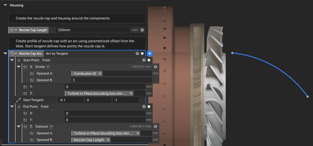
min Z point to ensure a clean mating surface.
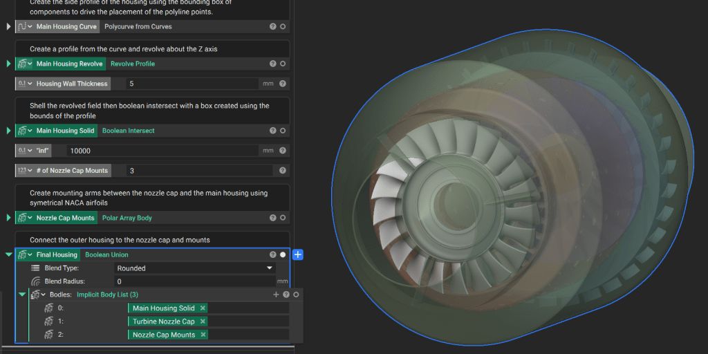
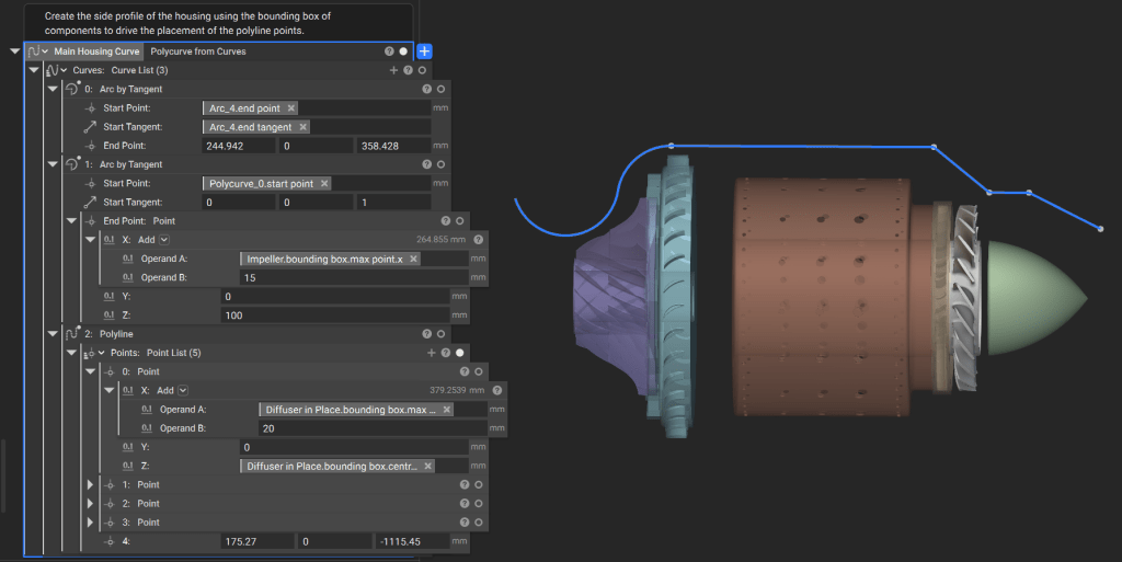
3. Generate the Outer Housing
The housing must encapsulate all internal components while allowing for specific wall thicknesses. Construct the Side Curve: Use the Polyline block and arcs to create the housing profile. Parametrize these curves based on component bounding boxes plus required offsets.Note: In production workflows, these curves are often driven by first-order equations governing the engine’s performance requirements.
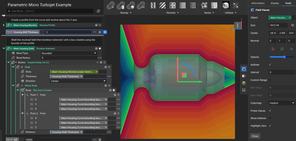
- Revolve the profile around the Z-axis to create an initial solid.
- Use the Shell block to hollow the geometry to your specified wall thickness.
- Finalize the geometry by performing a Boolean Intersect with a Box (generated from the side profile’s bounding box) to trim any infinite fields
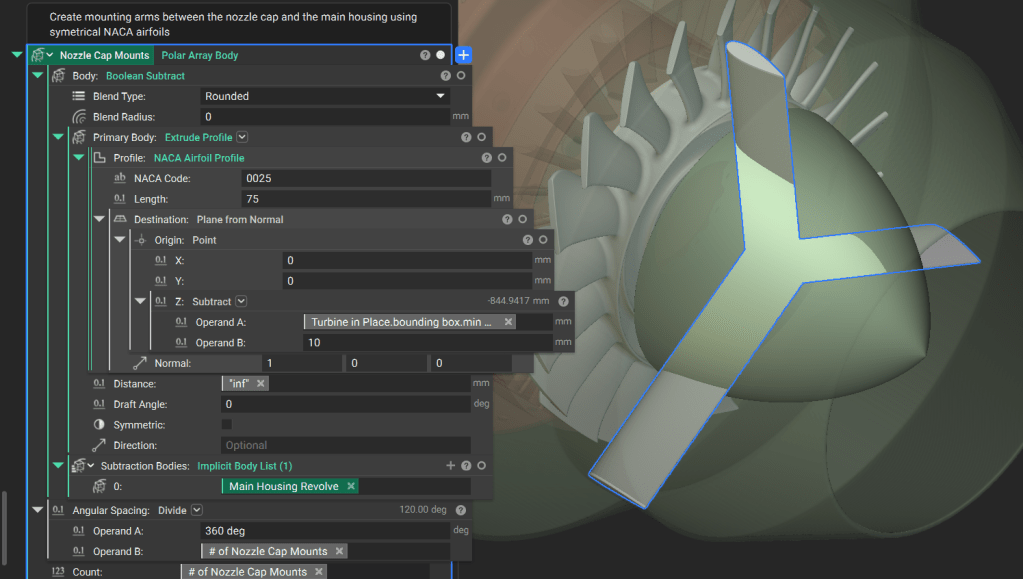
4. Generate Mounts and Union Housing
Mounting struts connect the internal nozzle cap to the outer housing. Model Struts: Use a Custom Block to generate a symmetrical 4-digit NACA airfoil profile. Extrude and Array:- Use Extrude Profile to create the strut geometry.
- Use Boolean Subtract to remove the portion of the struts that overlaps with the main housing field.
- Apply a Polar Array Body block to create the required number of struts around the Z-axis.