This lesson demonstrates how to use parametrized polylines and profiles in nTop to design a combustion chamber. You will learn best practices for creating complex arrays of holes and leveraging field modeling to ensure high-performance geometry.
Downloadable File: Parametric Combustor.ntop Report File Issue This file was last updated in nTop 5.37.3

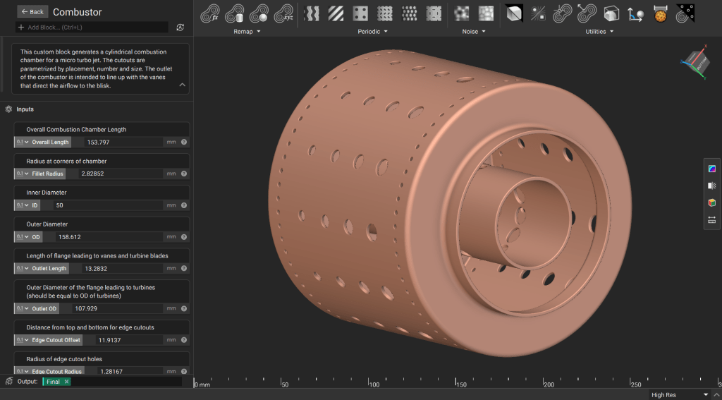
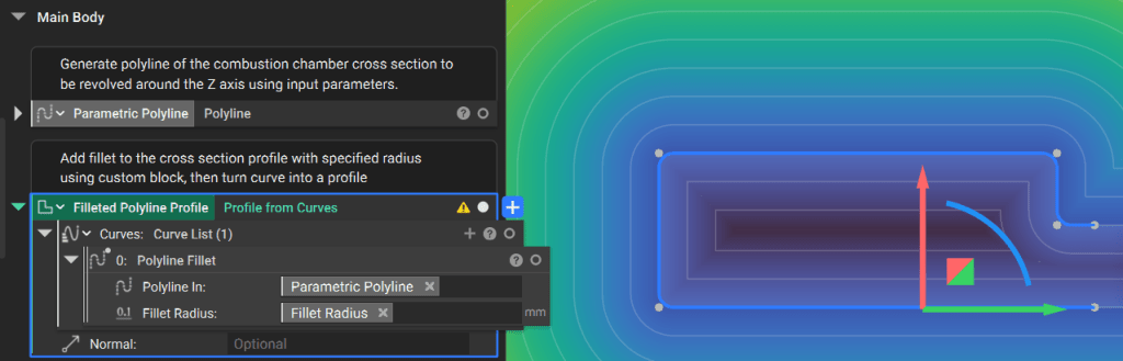
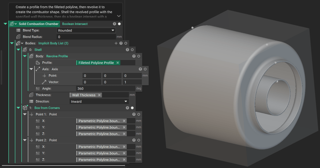
1. Generate the Main Body

Building a clean signed distance field (SDF) for an axisymmetric part starts with a well-defined profile. Define the Profile: Create a side profile of the combustor using a Polyline block. Use input parameters to drive the coordinates of each point. You can use similar techniques to parametrize control points for splines.
Apply a fillet to the polyline using the Polyline Fillet custom block and convert the curve into a Profile. Using an open profile ensures a clean field that projects predictably beyond the open ends.
Use the Revolve Profile block around the Z-axis to create solid geometry. Apply a Shell block to establish the specified wall thickness. Because the start and end lines of the profile are parallel, the resulting implicit body extends to infinity. Perform a Boolean Intersect with a box representing the design domain to trim the body to its final size.

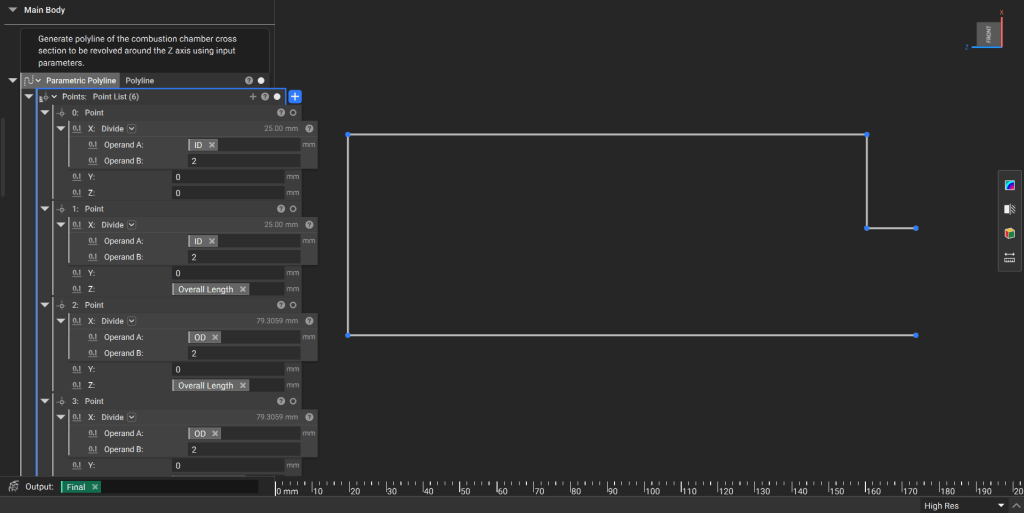
2. Generate the Cutout Tools

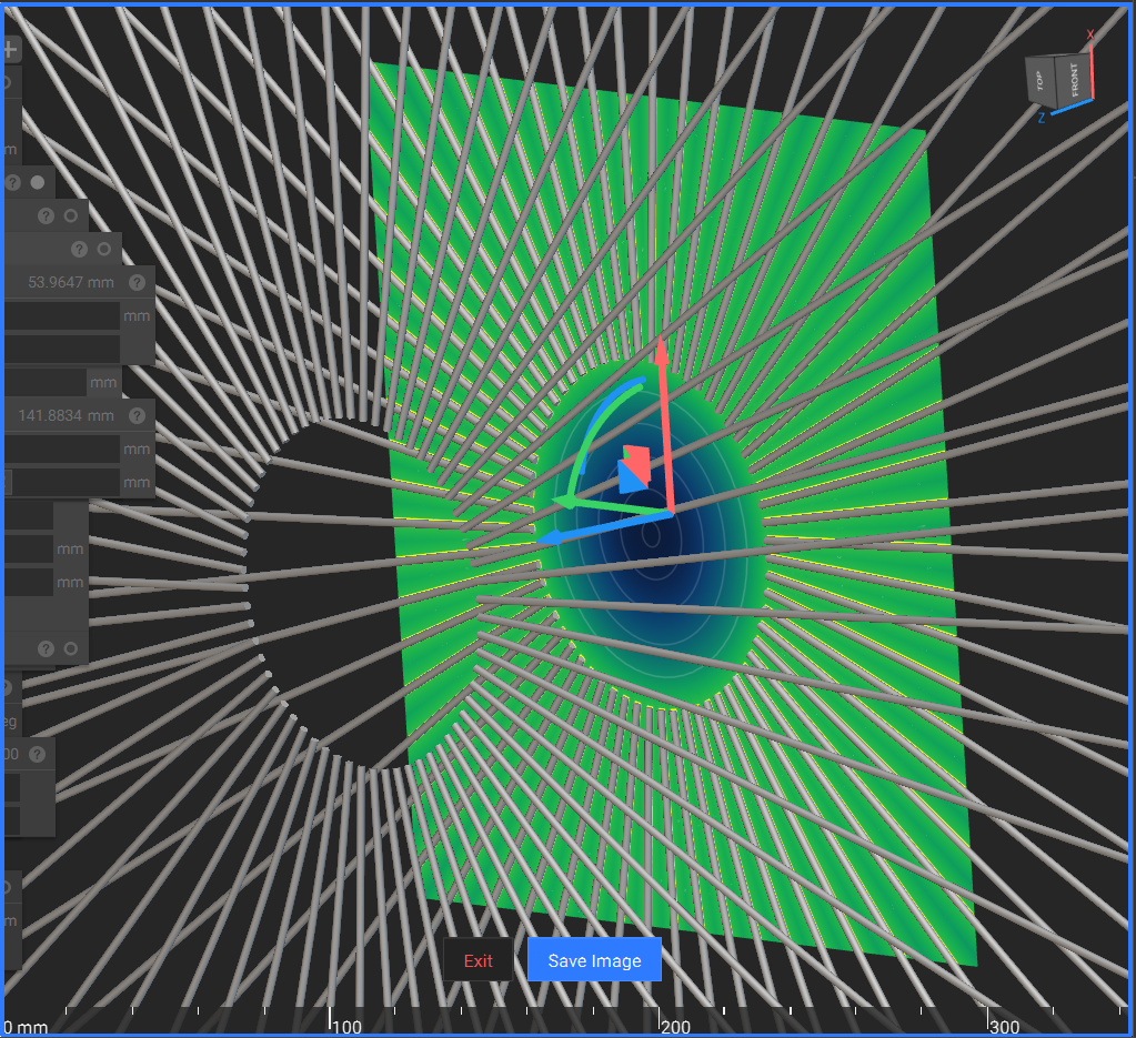
Create the geometry used to “drill” the cooling and intake holes through the chamber walls. Generate “infinite” Cylinder blocks based on your input parameters. Combine these using Boolean Union and then use the Polar Array Body block to position them around the chamber.
Tip: Rendering highly complex or “infinite” fields can be computationally taxing. Utilize the Field Viewer (Hotkey: F) or the Precise Render (Ctrl + H) feature to validate the geometry and see an accurate snapshot of the design.
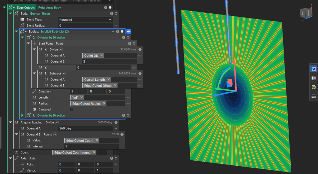
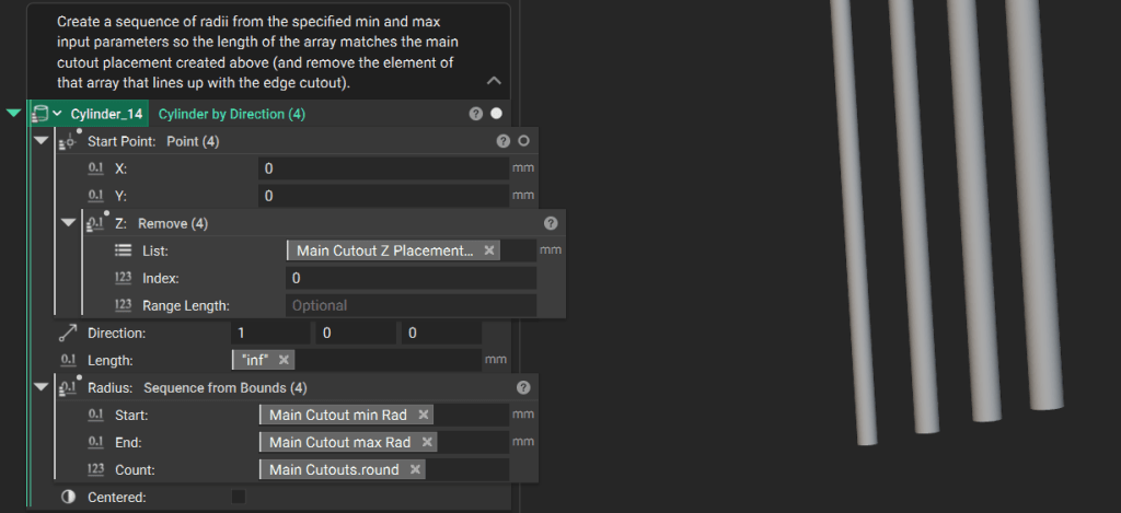
1. Generate an array of points along the Z-axis where the cutouts are required. 2. Create an array two elements longer than necessary, then remove the first and last elements to ensure correct spacing. 3. Create a corresponding array of radii for the cutouts based on your minimum and maximum specifications.
Tip: You can input a list of values to a block that typically produces one implicit body to produce a list of implicit bodies. Learn more about working with lists here.
Use a Polar Array Body block to create the final collection of cutout tools.

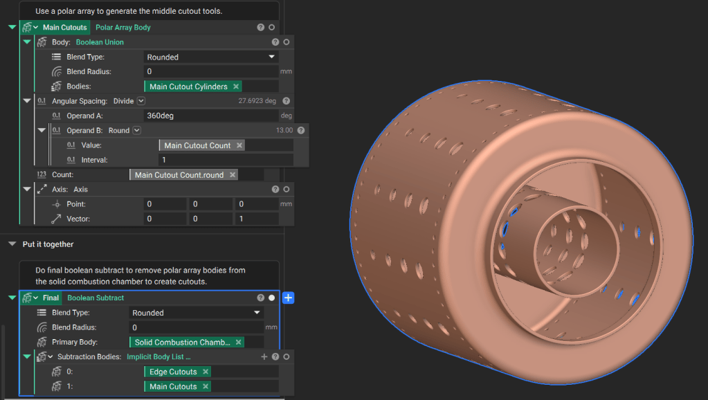
3. Final Assembly and Output

Perform a Boolean Subtract to remove the cutout tools from the solid combustion chamber body. To use this notebook in other workflows, drag the final implicit body variable into the Output section at the bottom of the notebook and move design parameters to the Inputs section at the top.