Once you are ready to print, it is time to use the Slice BodySlice Mesh, or Slice Lattice Graph block. All of these work very similarly; the only difference in inputs is that the Slice Body requires a Feature Size and Boundary.
To slice an Implicit Body, Graph, or Mesh. If you would want to slice an implicit body. Drag and drop the Implicit Body in the Body input, which will slice with the Layer Height and Feature Size input parameters. If your body has portions below 0 in the Z direction, select “Include Negative Z.”  You can also add a Frame if you want to slice at an angle or a different starting location. In the Frame input, add a reference point to generate the slice stack using the Frame block.

Black and White Image Slicing

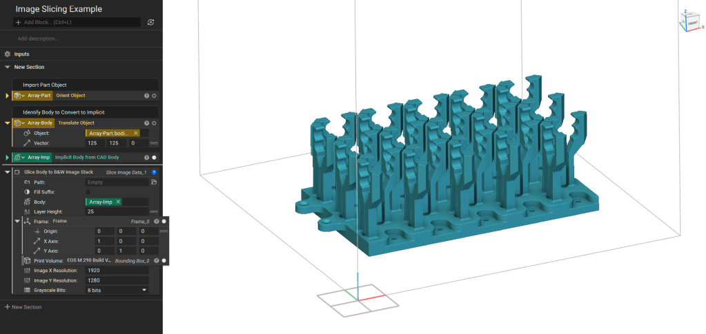
If you need a Black-and-White Image Stack, you can create one with the Slice Body to B&W Image Stack block. First, the implicit bodies on the build volume are oriented, and this list is translated to the Implicit input in the block.
Fill Suffix:
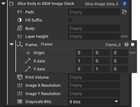
  • Toggled On: Names the files: “slice_001”, where the total number of slices determines the number of 0’s before the slice number. 
  • Toggled Off: The files are named “slice_1”, with no 0’s. 
Layer Height: Define the spacing between the layers. You may need to check the printer settings for the appropriate range of heights. Frame: This is the coordinate system for the build plate. Depending on the printer settings, it may need to be edited. The Resolution is the number of pixels in the X and Y directions. This value may change depending on your printer and desired resolution. The max image resolution support is 1 billion pixels.
After filling in all the inputs, the block saves the resulting *.png file format image stack in the zip folder defined earlier.