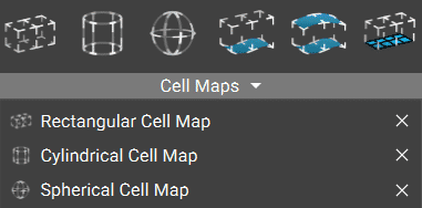
Rectangular Cell Map
The Rectangular Cell Map block generates a cell map across the input volume with cells of defined Cell Size in rectangular coordinates. This map serves as a layout for the lattice Unit Cells.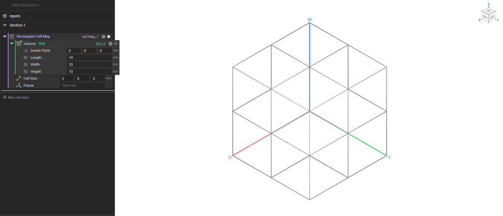
Note: The default Cell Map’s starting point is the Minimum point of the body’s bounding box. To change this starting point or the cell map’s orientation, add a Frame or Plane block to the optional Frame input.
Cylindrical Cell Map
The Cylindrical Cell Map block generates a Cell Map with a cylindrical coordinate system that covers the entire input volume with cells using the specified Cell radius (U), Cell height(V), and Arc count (W). The Cell Map edges will be default curved to the cylindrical coordinate system. Check the Linearinput to generate straight edges only.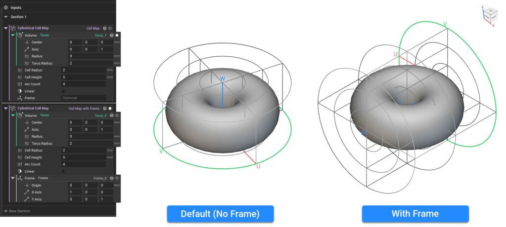
Note: The default Cell Map’s starting point is auto-computed based on the volume’s principal axes about the center of mass. To change this starting point or the cell map’s orientation, add a Frame block to the optional Frame input.
Spherical Cell Map
The Spherical Cell Map generates a Cell Map with a spherical coordinate system that spans the entire input volume with cells using the specified Cell radius (U), Latitude count (V), and Longitude count(W). The Cell Map edges will be default curved to the cylindrical coordinate system. Check the Linearinput to generate straight edges only.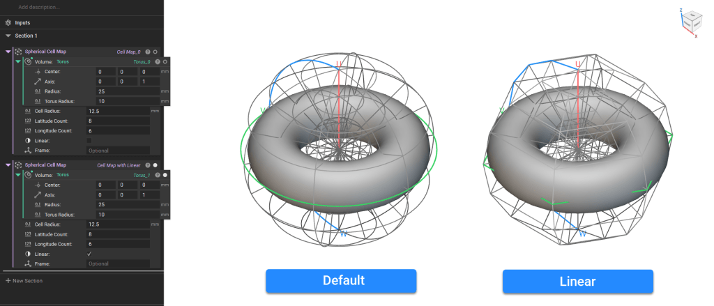
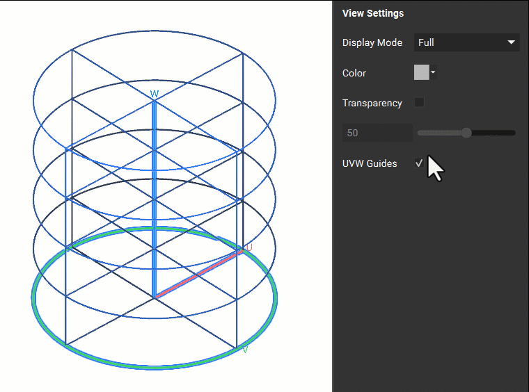
View Settings
When creating the Cell Map, you can isolate the block using ‘I’ and view the Full Map or Navigate the Map using the heads-up display. The Navigate and Full display modes are available in the Display tab of the Right Panel. The Navigate mode allows you to view individual cells.