Issue:
The lattice from CAD face doesn’t match up with the CAD face shape as I expected it to.Applies to:
- Cell Map
- Lattices
- CAD faces
Cause:
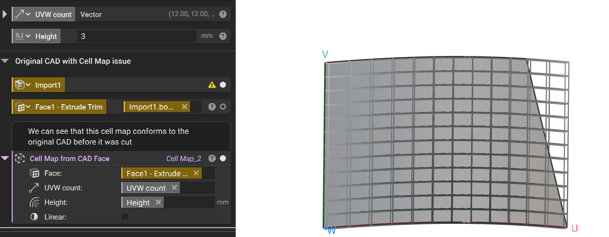
nTop will use the UVW parameterization provided in the CAD file we receive. A face that is trimmed still carries the underlying UVW of its untrimmed “parent”; therefore, you’ll see that the cell map extends past your face. Trimming the lattice may result in partial/cut-off unit cells.Solution:
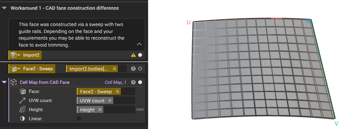
To achieve a more desirable cell map, we recommend trying the following options:- The best solution is to modify the original CAD creation. We recommend changing the design process to avoid the use of trimming. Tools like lofts, sweeps, and revolves will improve UVW parameterization. In the two images below, you can see how the CAD body appears to be the same. However, the original body is trimmed, and the modified body was created with a sweep. This results in an ideal cell map versus the over-extending cell map.
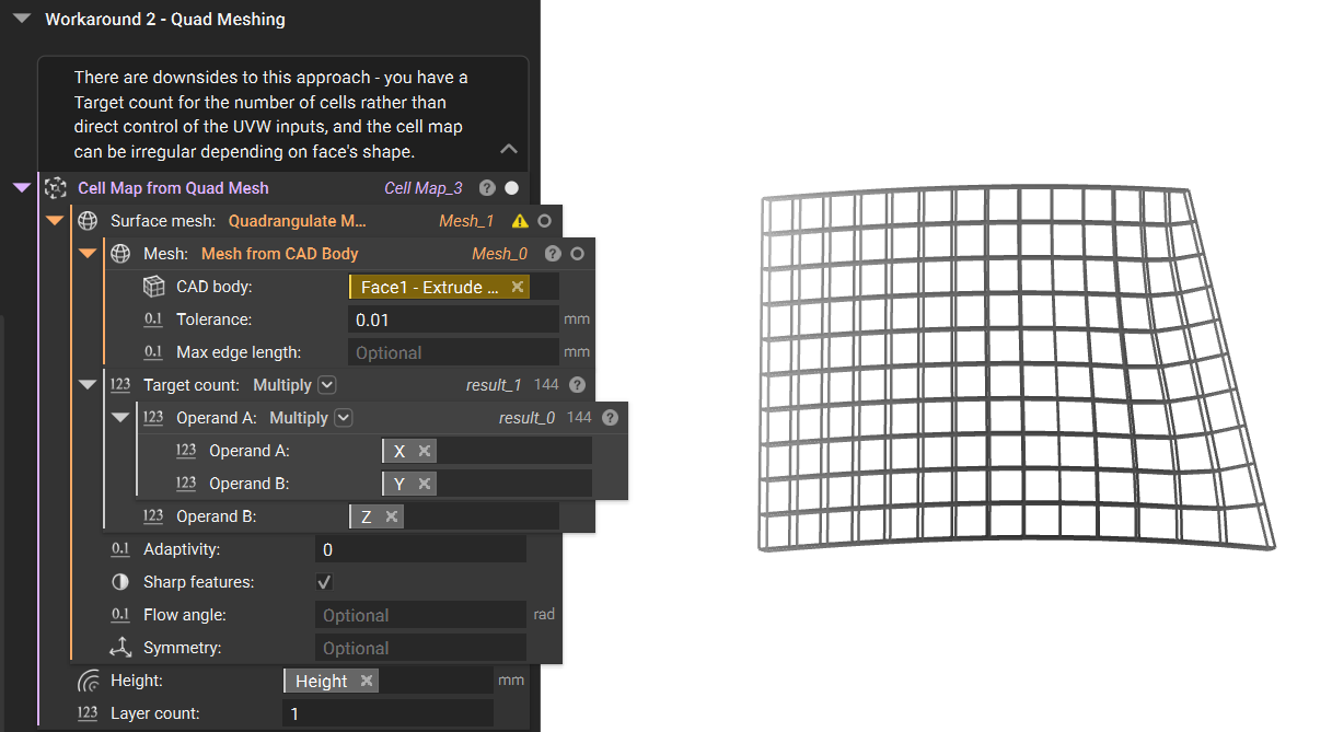
- The other option is to modify the surface in nTop. We can create a quad mesh of the surface to conform more to our intended result. Increasing the Quadrangulate Mesh block’s target count will result in a finer mesh that is more conformal around boundary curves, but this will also reduce the size of the quads. However, this solution has the drawback of being unable to control the UV inputs directly, and depending on the curvature of the CAD Face, the resulting cell map may be a disordered, non-uniform grid.
 Are you still having issues? Contact the support team, and we’ll be happy to help!