Objective:
Perforate using a unit cell on any surfaceApplies to:
- Orienting Unit Cells
Procedure:
- Preparing the Geometry and Unit Cell
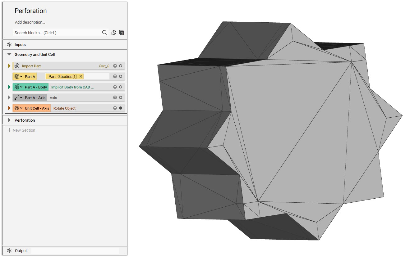
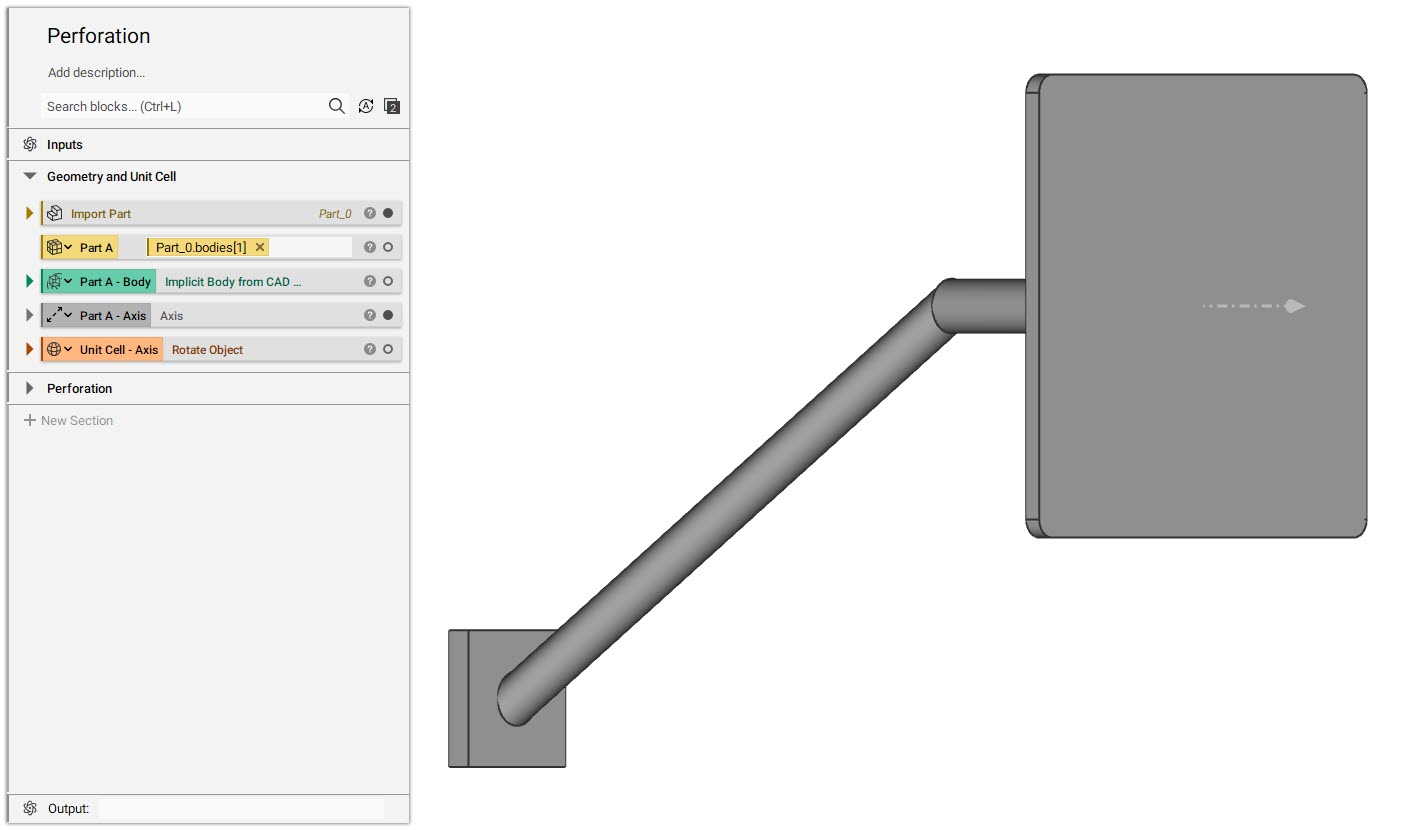
- Drag and drop the CAD Body variable from the properties panel of the Import Part block.
- Convert the CAD body to Implicit Body and make it a variable to be reused.
- Create an Axisat the center of the face and normal to the CAD face.
- Import the custom blocks:
- CB - Orient Unit Cell to Plane v2-3
- CB - Orient Unit Cell to Plane v3.4
- Selecting Geometry for the CB
- Select the CAD Face on which you would want to place the unit cell and CAD Edge list for the Keep Out Zone to be used in the CB (How to work with CAD bodies)
 Tip: Don’t worry if you select an additional CAD Face while selecting CAD Edges, you can easily delete it later from the Notebook.
- Insert the Custom block by searching CB - Orient Unit Cell to Plane in the Search box and choose the version you would like to use based on the inputs below:
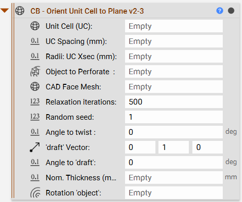
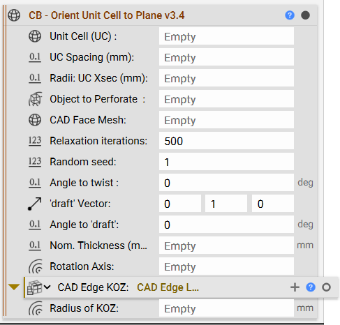 - **Unit Cell (UC):**The unit cell that was prepared by aligning to Z-axis in the above step.
- UC Spacing (mm): The spacing between two unit cells/perforations. Make sure you enter “mm” after the value for the block to not throw an invalid units error.
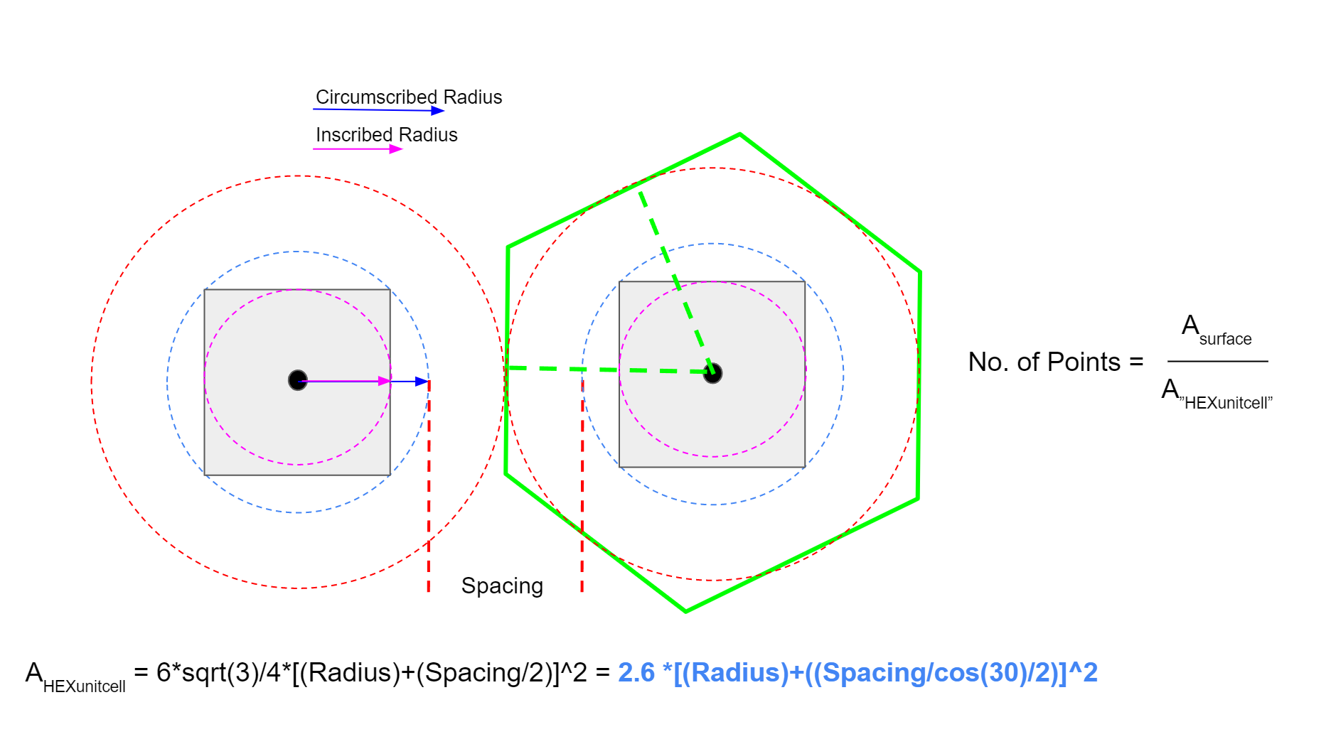
- **Radii: UC Xsec (mm):**The value can be chosen between the minimum and maximum radii of an inscribed circle or circumscribed circle on a cross-section of your unit cell.
- **Object to Perforate:**This input is for the implicit body that you wish to perforate with the unit cell.
- **CAD Face Mesh:**Use the CAD Face Mesh selected to place your unit cell.
- **Relaxation Iterations and Random Seed:**These inputs are to evenly distribute and add randomness to the point distribution.
- **Angle to twist:**The angle at which the unit cell has to be twisted about its own axis.
- ‘draft’ vector and Angle to ‘draft’: The vector in which you want to rotate/tilt your unit cell and the handle to rotate your unit cell on the defined vector.
- Nominal part thickness of the section you are perforating (mm): The thickness of the body being perforated. This can be used as a translation distance from the surface along with its axis.
- **Rotate ‘object’:**The primary axis of the object you want to perforate
- **CAD Edge KOZ:**Use the CAD Edges where you wish to keep out the unit cell from. This will be used to remove the points near the edges.
- **Radius of KOZ:**The radius you want to define the exclusion zone is the CAD edge.
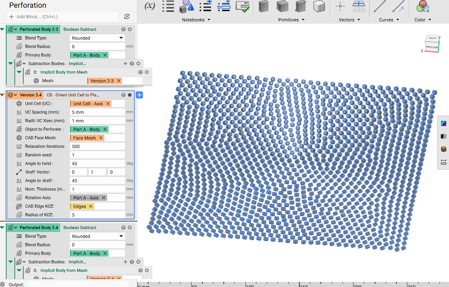 Once the unit cells are in place, we can convert the mesh to an implicit body, and then use a Boolean Subtract to perforate the surface.
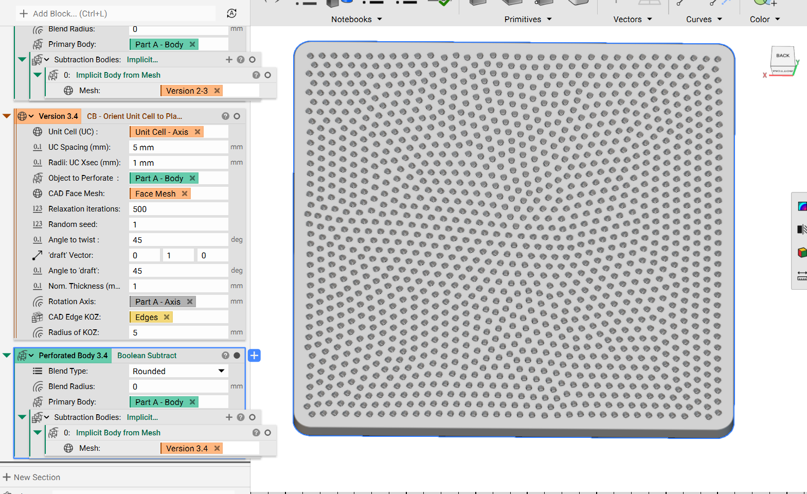 Feel free to right-click and export the custom block to see what’s inside and that’s it! You’ve successfully perforated with unit cell mesh.
Are you still having issues? Contact the support team, and we’ll be happy to help!
Feel free to right-click and export the custom block to see what’s inside and that’s it! You’ve successfully perforated with unit cell mesh.
Are you still having issues? Contact the support team, and we’ll be happy to help!