Objective:
How to transition a structural ribbing workflow from the old to new latticing blocksApplies to:
- Conformal Lattice from CAD Face
- Cell Map on CAD Face
Procedure:
1. Import your CAD part using the Import Part block and then create variables of the CAD’s faces to be used in multiple places. (How to work with CAD bodies) 2. Creating a conformal lattice in the old and new lattice pipelines.| Old Lattice Blocks | New Lattice Blocks |
|---|---|
| Reparametrize CAD Face | Cell Map from CAD Face |
| Conformal Lattice from CAD Face [deprecated] | Periodic Lattice |
| Thicken Body |

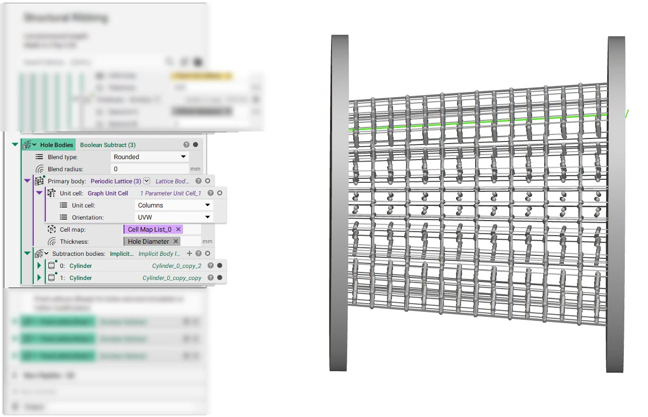
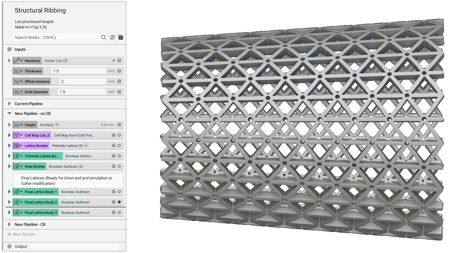
- We use the Periodic Lattice block and Columns as Graph Unit Cell to create columns that can be used to Boolean subtract from the lattice to generate holes.
Notes:
- The new pipeline allows other unit cells such as TPMS unit cells and custom implicit unit cells. This was not possible with the old lattice pipeline.
- There is now a difference in the unit cells mapping to the CAD face.
- Old: Only the unit cell cube corners were mapped, and nodes within a cell were interpolated within the mapped cube.
- New: All unit cell nodes are now being mapped to the CAD face (and offset accord to face normal).
Download the Example file:
- How to create a periodic lattice
- How to build a structural lattice on a CAD face
- How to import parts and data into nTop