Objective:
This article explains how to generate advanced swept surfaces between two rail curves using a spine curve. By utilizing the Conic Section Sweep, Conic Section Sweep by Tangent, and Cubic Bezier Section Sweep blocks, you can create high-fidelity aerodynamic profiles and smooth transitions for complex modeling workflowsApplies to:
- Surfacing
- Workflows: Aerodynamics, Fluid Flow Management, Architectural Design
Procedure:
1. Prepare Your Curves
Before using the sweep blocks, ensure you have the following curve inputs prepared:- Rail 1 and Rail 2: These define the outer boundaries of the sweep. Note that these cannot be closed curves.
- Spine: This curve acts as the origin or axis for the sweep operation.
2. Select the Appropriate Sweep Block
Choose the block that best fits your design requirements:-
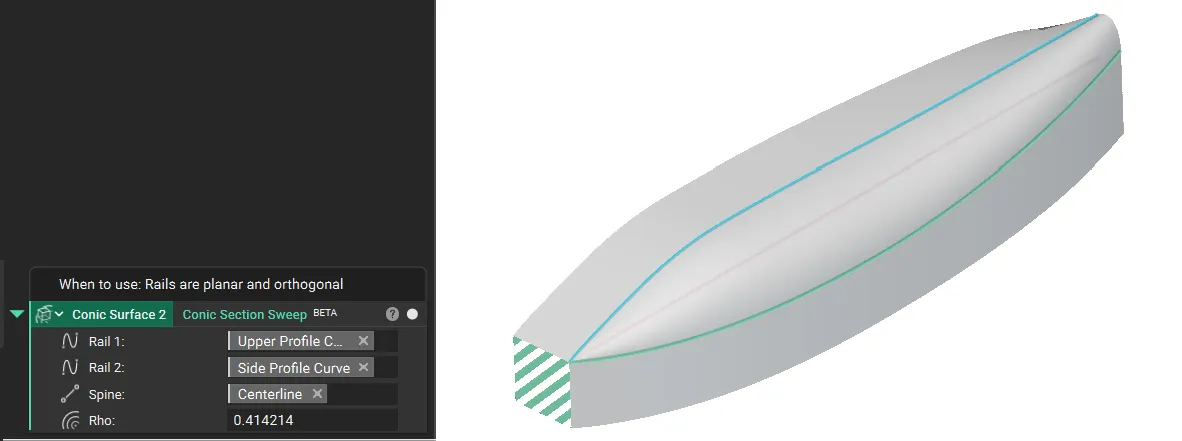
Standard Control: Use Conic Section Sweep.
- This creates a swept conic section where the resulting geometry extends beyond the rails along the spine’s tangents.
- Use this for when Rails that are planar and orthogonal
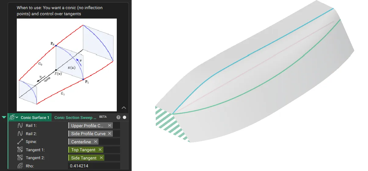
 - Tangency Control: Use Conic Section Sweep by Tangent.
- Select this when you need precise control over the surface tangency to strictly define the “take-off” angle of the surface from the rails.
- This block accepts tangent vector fields at each rail.
- Use this when you want a conic (no inflection points) and control over tangents
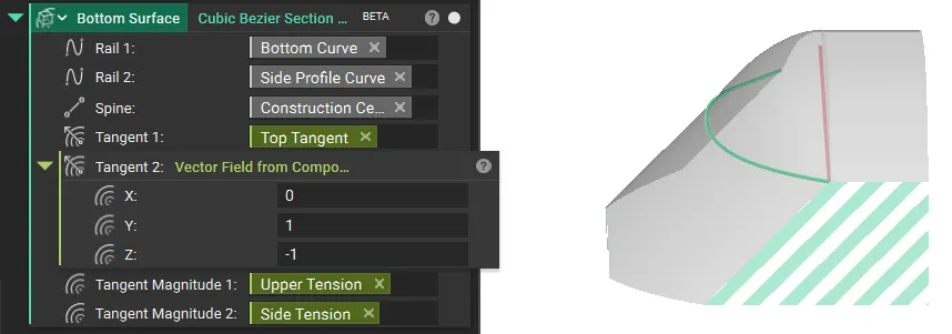
 - Curvature and Smoothness Control: Use Cubic Bezier Section Sweep.
- Select this for high-fidelity control over surface continuity.
- This block uses spatially varying tangent vector fields and magnitude fields at each rail to control smoothness.
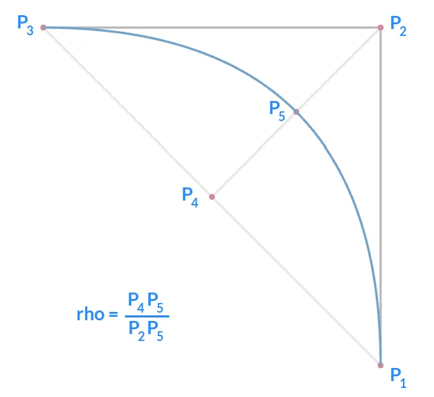
 ### 3. Configure the Shape Parameters (Rho)
For the conic sweep blocks, the cross-sectional shape is defined by the Rho value. You can define this as a constant value or use a Ramp block to vary the shape spatially along the sweep.
### 3. Configure the Shape Parameters (Rho)
For the conic sweep blocks, the cross-sectional shape is defined by the Rho value. You can define this as a constant value or use a Ramp block to vary the shape spatially along the sweep.
Rho Value | Resulting Curve Type | Example |
| ρ<0.5 | Ellipse | 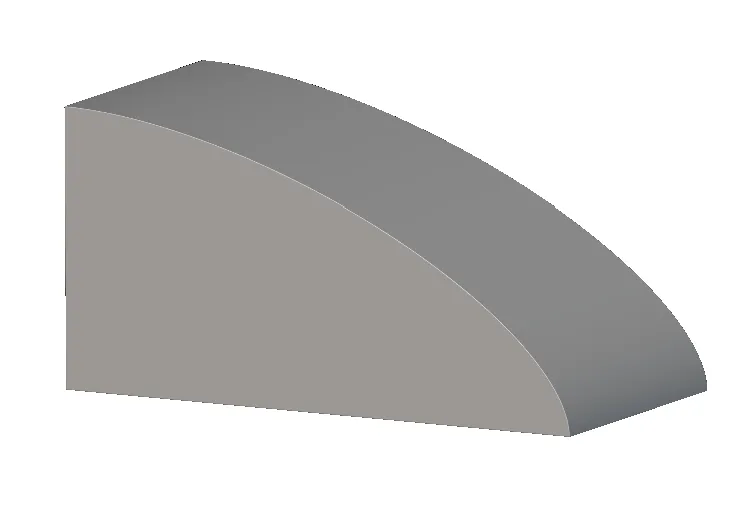 |
| ρ=0.5 | Parabola | 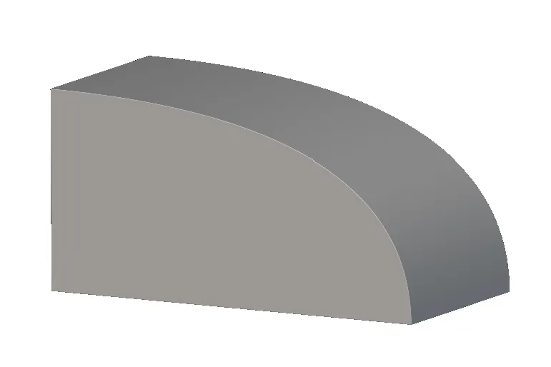 |
| ρ>0.5 | Hyperbola | 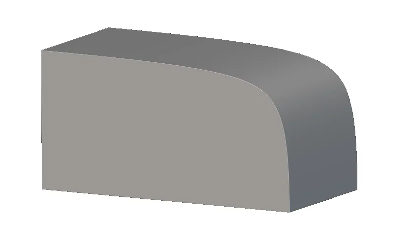 |
4. Adjust Tangency (Optional)
If using the Cubic Bezier Section Sweep:- Adjust the Tangent Magnitude inputs.
- Note that these values are relative to the in-plane distance between the rails.
- A value of 1.0 indicates that the handle length equals the distance between the rails at that specific point.
5. Finalize the Body
The output of these blocks is an implicit surface. To create a solid, closed body suitable for downstream operations:- Use the Boolean Intersect block to close the surfaces.
Best Practices and Troubleshooting
Angle Thresholds- Avoid Steep Angles: We recommend avoiding steep angles between the rail curves and the spine. This prevents unexpected results during shelling or offsetting downstream.
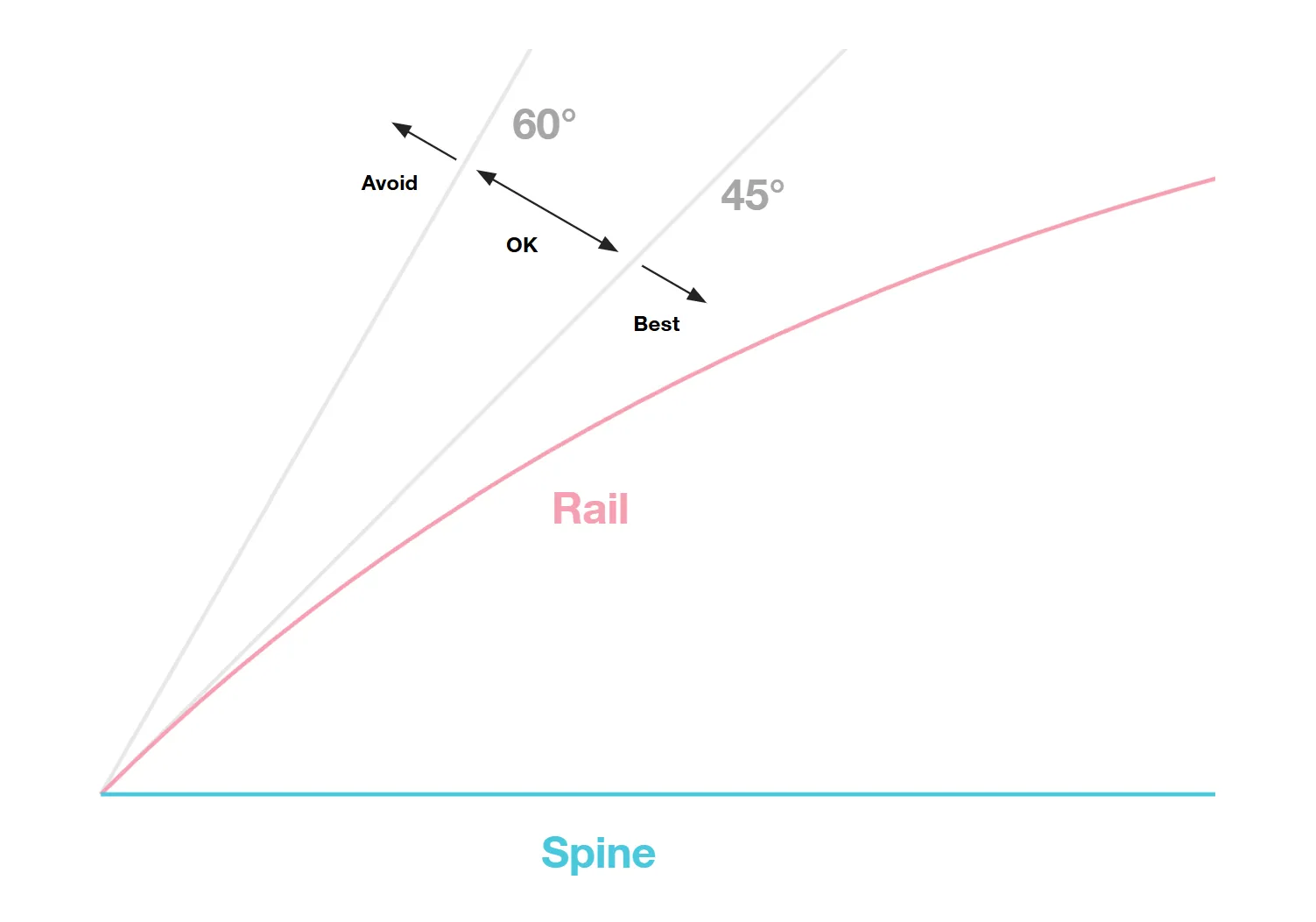
- Rule of Thumb: Maintain an angle threshold between 45° and 60°.
- “Rays from the axis…” Error: This indicates that the rails are perpendicular to the spine at some point. Rails cannot be perpendicular to the spine. Ensure that rays projected from the axis along the specified direction intersect the curve only once.
- “Improperly configured inputs” Error: This often indicates that the geometry is self-intersecting relative to the axis.
- Closed Rails: Ensure Rail 1 and Rail 2 are open curves. If they are closed, replace them with open curves to resolve the error.