Question:
Is blending edges or adding a fillet to lattice nodes and beams possible?Applies to:
- Implicit modeling
Answer:
We recommend three methods for applying fillets to lattice structures. This article will walk through each method to help show their differing results.Method 1: Blend Intersections
This method is only applicable for Graph Unit Cells.- Create your Periodic Lattice with a Graph Unit Cell or a 2D Unit Cell (How to create a periodic lattice and Guide to Rib Design)
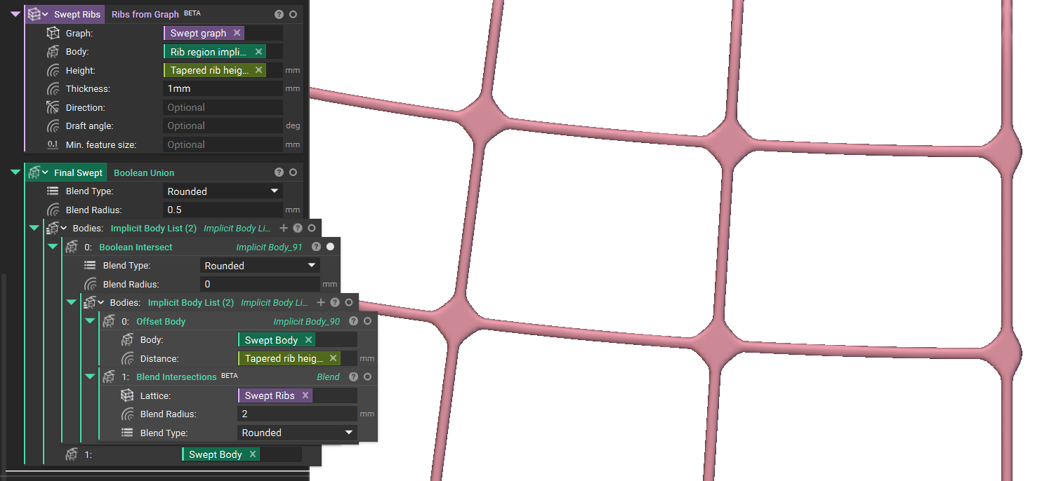
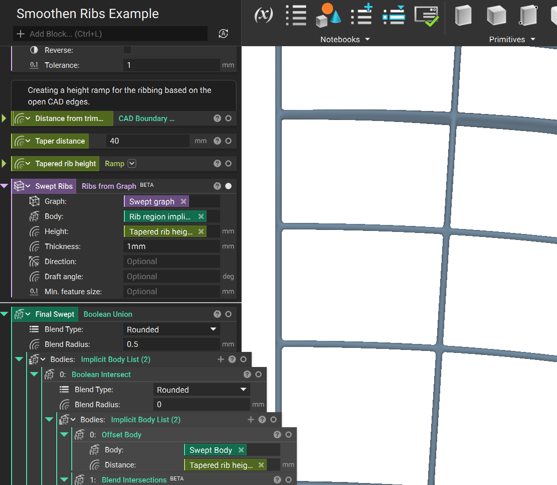 2. Add a Blend Intersections block. Lattice input is the Swept Ribs we created from the Ribs from the Graph block. Blend radius the filetting we are applying to the Ribs.
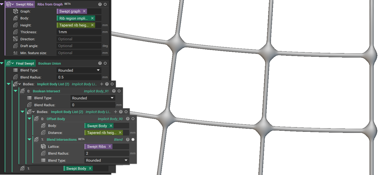
- Boolean Intersect with Offset Body and the Height as distance input.
Method 2: Custom Unit Cell (Resource Intensive)
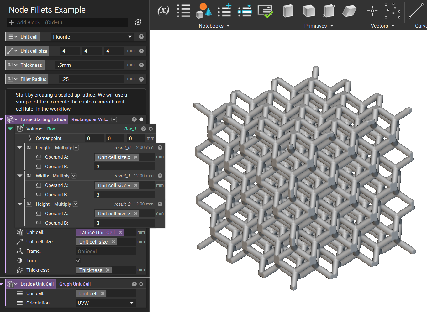
- This method is based on smoothening an unit cell and then using that unit cell to create a lattice. For this example, we start with a generic Rectangular Volume Lattice. The lattice volume is scaled up to create a correctly proportioned unit cell later in the workflow. We convert some of the inputs from the workflow into variables for easy lattice modification at the end.
Note: The Custom Unit Cell Method requires significant computation power and takes longer to process.
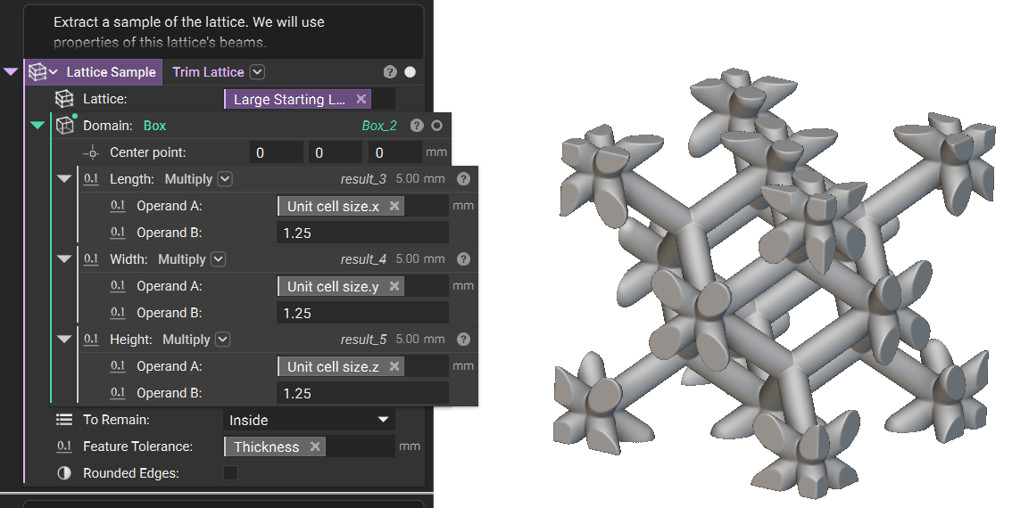
- Next, we use a Trim Lattice and Box block to create a sample section of the enlarged lattice. The Box is larger than the unit cell to ensure all of the necessary beams will be present when creating the lattice.
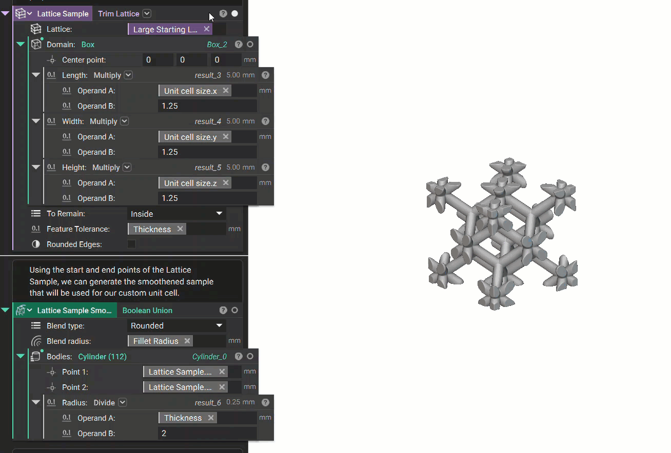
- Using the start and end points of the lattice sample, we can generate cylinders in place of the original beams. This will allow us to apply the radius to the sample when the cylinders are combined in the Boolean Union.
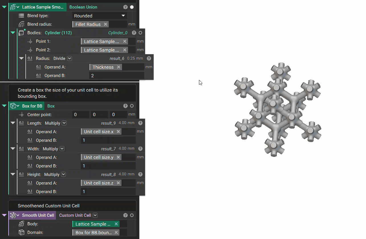
- Now that we have the smooth sample lattice, we can create a Box the size of the unit cell. The Bounding Box of that Box is now the defining boundary of our Custom Unit Cell.
- We can now generate the smooth lattice using the Rectangular Volume Lattice. For this example, we just used a Box as the body to generate the lattice from. Depending on your design, this may be the final necessary step. To close the open beams, continue with the last two steps.
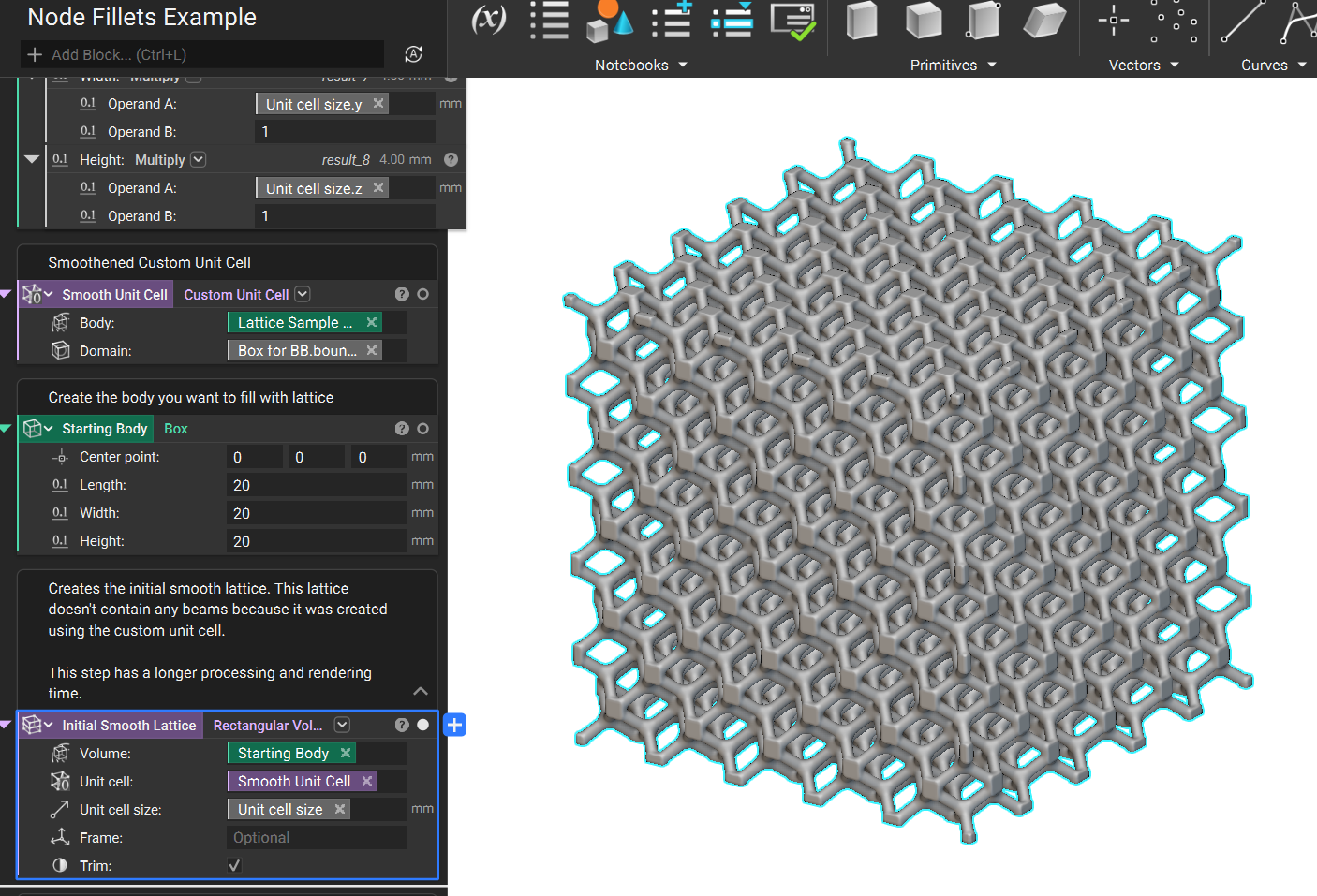
- The Initial Smooth Lattice is made of the Custom Unit Cell we generated. This contains no beams because it is made of the merged Cylinders. To fix this in the next step, we can create a Reference Lattice using the original Unit Cell. Now that this lattice has beams, we can use the Filter Beams by Connectivity block to remove the open beams.
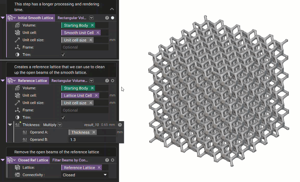
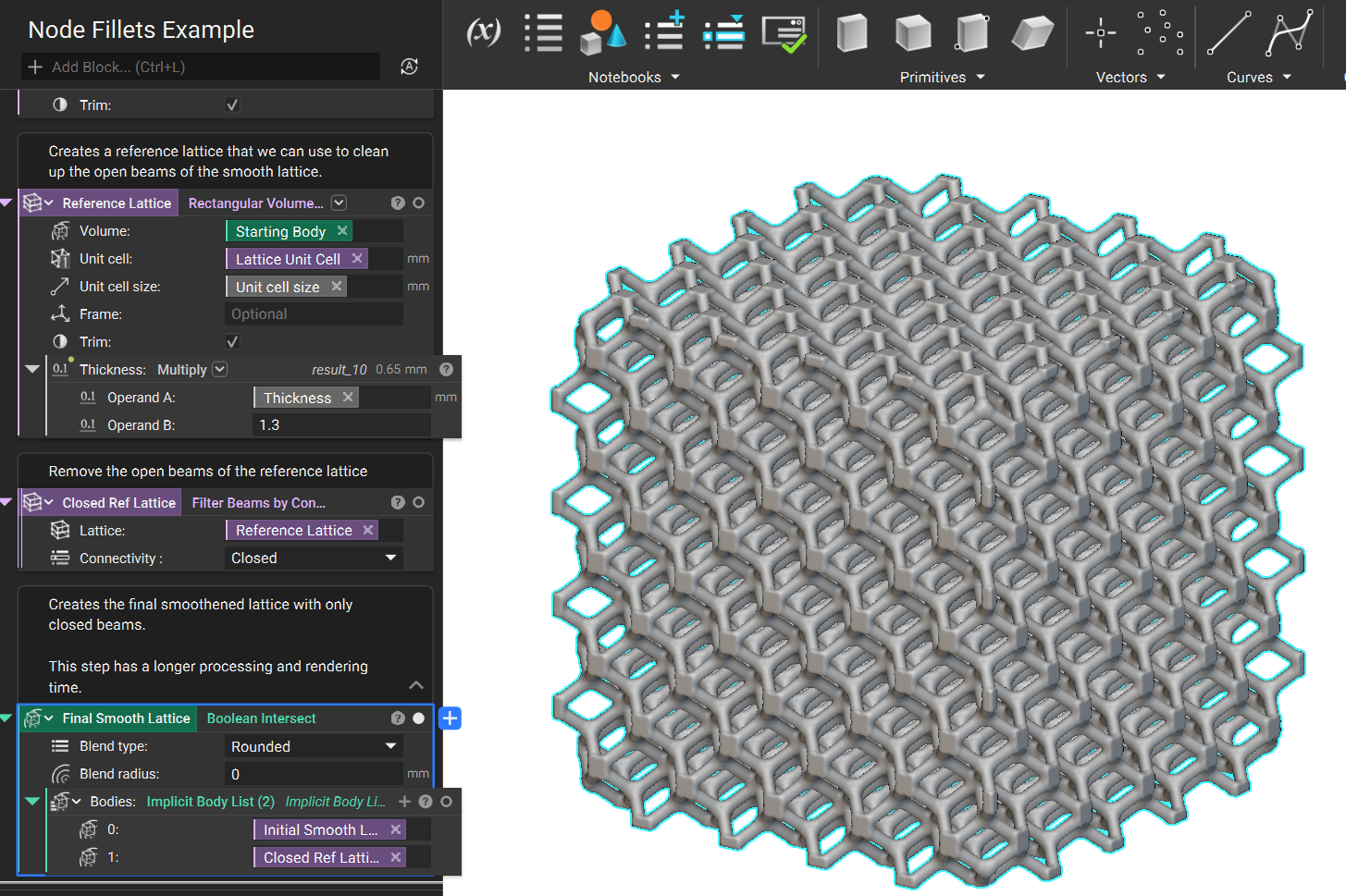
- The final step is to use a Boolean Intersect with the Initial Smooth Lattice and the Closed Reference Lattice. This results in the lattice having fillets at the nodes with the removed open beams.
 Are you still having issues? Contact the support team, and we’ll be happy to help!
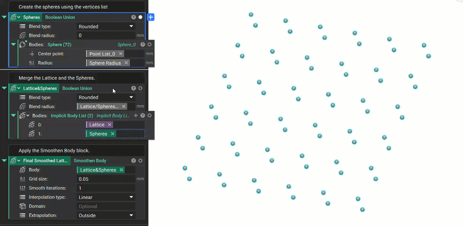
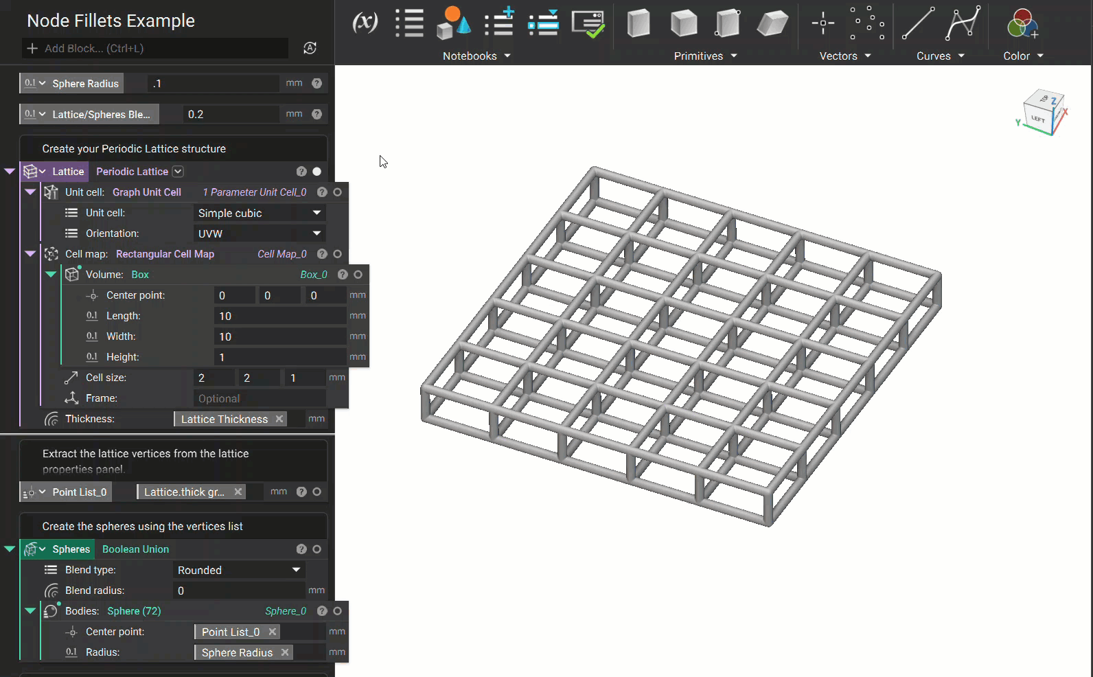
Method 3: Spheres
- Start with any lattice structure you want to thicken the nodes. For this example, we will be using a standard Periodic Lattice. You can see some of the inputs from the workflow have been turned into variables for easy lattice modification at the end.
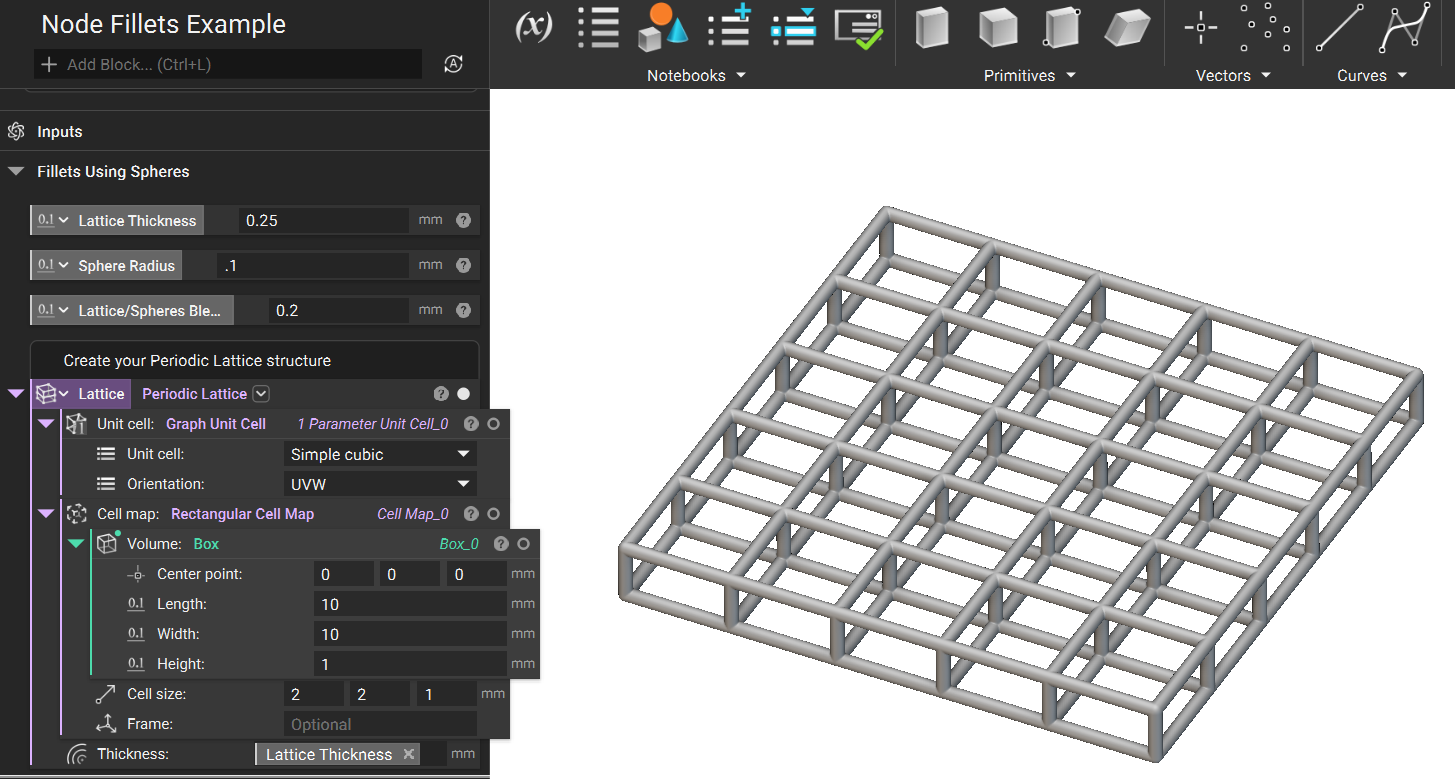
- We will extract the vertices from the properties panel using this lattice. These vertices are then used to generate Spheres, which we will Boolean Union together to create one body.
- To generate the final lattice, we use a Boolean Union to combine the Spheres with the Periodic Lattice. Then, using a Smoothen Body block, we can create smooth fillets between the nodes and the beams. The fillet size can be adjusted using the Grid size and Smooth iterations inputs. A larger grid size makes more drastic fillets, while a smaller one will create gentler fillets, increasing run-time.