Objective:
Learn how to create holes in your part that are varied in size and location. This workflow can be accomplished using the Perforate Body or Perforate Body from CAD Face toolkits. This tutorial goes through each step in the process to allow you to edit the workflow to your specific application and gain an understanding of what happens ‘under the hood’ in these toolkits.Applies to:
- Implicit modeling
Procedure:
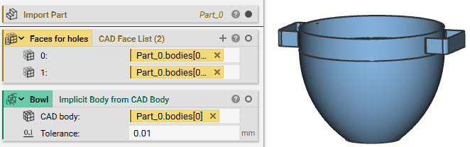
1. Set up:- Import your model.
- Extract the faces you want to be perforated
- This process is easier with a CAD model, due to face selection, but can also be done with a mesh using the Filter Mesh by Floodfill block to select specific areas.
- Create an Implicit body of the entire model (to be used in Step 4)
 2. Mesh: Mesh the faces that you want to perforate. These steps may look different depending on your geometry.
- Add a Mesh from CAD Body block and insert the CAD Face List
- Add a Merge Meshes block and insert the Mesh from CAD Body block to get rid of the List
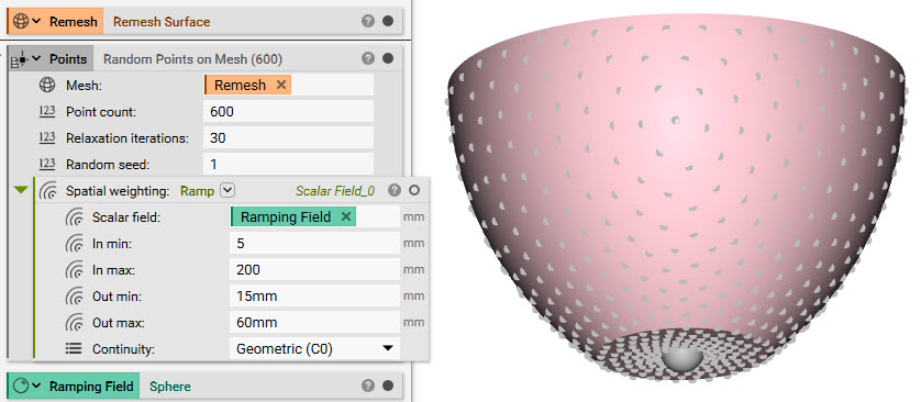
- Add a Remesh Surface block and insert the Merge Meshes block to create a uniform mesh for better point creation
- Add a Random Points on Mesh block
- Mesh: Remesh Surface
- Point Count: 600
- To vary the point spacing: Add a Ramp block to the Spatial Weighting input
- Scalar Field: Add a Sphere block (The holes will vary spatially in distance using this sphere as the field)
- Center Point: (0,0,0)
- Radius: 20 mm
- In min: 5mm, In max: 200 mm
- Out min: 15 mm, Out max: 60 mm
- Scalar Field: Add a Sphere block (The holes will vary spatially in distance using this sphere as the field)
 4. Set up the lattice: This step creates a lattice beam at each hole location. The thickness of the lattice corresponds to the size of the hole.
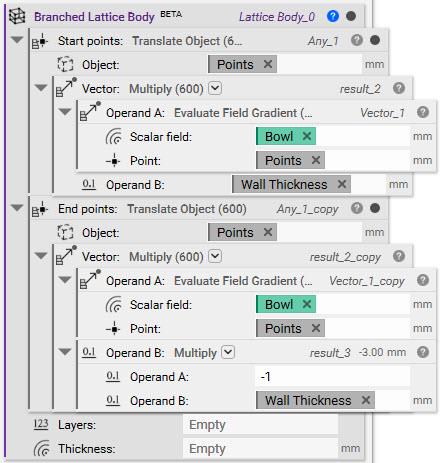
- Add a Branched Lattice Body block (this is a beta block)
- Delete the auto-generated lists in the Start points and End points inputs
- Add an Evaluate Field Gradient block (this block evaluates the field of our implicit body at each point location)
- Scalar Field: Use the Implicit Model we created of the entire body (in this workflow, it is called ‘Bowl’)
- Point: Insert the Random Points on Mesh from Step 3
- Now that the points are evaluated on the field, we multiply them by the thickness of our part (the wall thickness is the minimum value if we want the holes to cut entirely through our part)
- Add a Multiply block
- Input A: Evaluate Field Gradient block
- Input B: (right-click and select ‘Create Variable’ on this input)
- Change the name to Wall Thickness
- Set the value to 3 mm
- Add a Translate Object block
- Object: Insert the Random Points on Mesh from Step 3
- Vector: Insert the Multiply block
- Insert the Translate Object block into the Branched Lattice Body Start Points input
 4b. Translate the Points Inward: To translate the points in the opposite direction, we duplicate the blocks we created and multiply the Wall Thickness by -1 to change the direction of the translation.
- Right-click on the Translate Object block and select ‘Duplicate’
- Delete the Wall Thickness variable from the Operand B input
- Add a Multiply block and insert it into the Operand B input
- Set Operand A to -1 and Operand B to the Wall Thickness variable
- Insert the Translate Object block into the End Points input of the Branched Lattice Body block
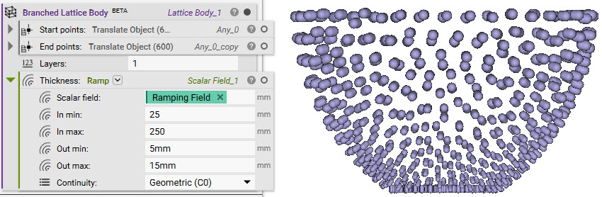
 5. Layers and hole size
- Set the layer value to 1. This means the lattice created between the points will only have one branch
- In the Thickness input, add a Ramp block to vary the size of the lattice, which will be the size of the holes
- Use the same Scalar Field from Step 3, the Sphere.
- In min: 25mm, In max: 250mm
- Out min: 5mm, Out max: 15mm
 6. Turn the bowl into a colander
- Add a Boolean Subtract block
- Set the Primary body to the ‘Bowl’ (the Implicit body of the entire model)
- Open up the Properties of the Branched Lattice Body and take out the ‘Implicit’ chip. Insert it into the Subtraction Body input
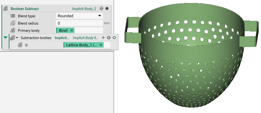 And that’s it! You’ve successfully perforated the bowl with holes that vary in size and spacing.
Are you still having issues? Contact the support team, and we’ll be happy to help!
And that’s it! You’ve successfully perforated the bowl with holes that vary in size and spacing.
Are you still having issues? Contact the support team, and we’ll be happy to help!