Objective:
Learn how to reshape plumbing geometry to increase performance by using CFD data. See More on this Topic at the bottom of this article for similar examples of the process, blocks, and general workflow used. It is recommended that you review these first as the write-up below assumes a basic understanding of the processes used.Outcome:
Comparing the results in Fluent and after just one iteration of reshaping the inlet and outlet piping geometries, the pressure drop on the cold & hot sides decreased by 38% and 20% respectively, while the average heat transfer coefficient inside the heat exchanger core increased by about 34%. A side-by-side comparison of the geometry changes can be seen in Image #1. This was accomplished by importing a velocity point map from CFD results, removing regions of low velocity, and generating new geometry from the truncated field.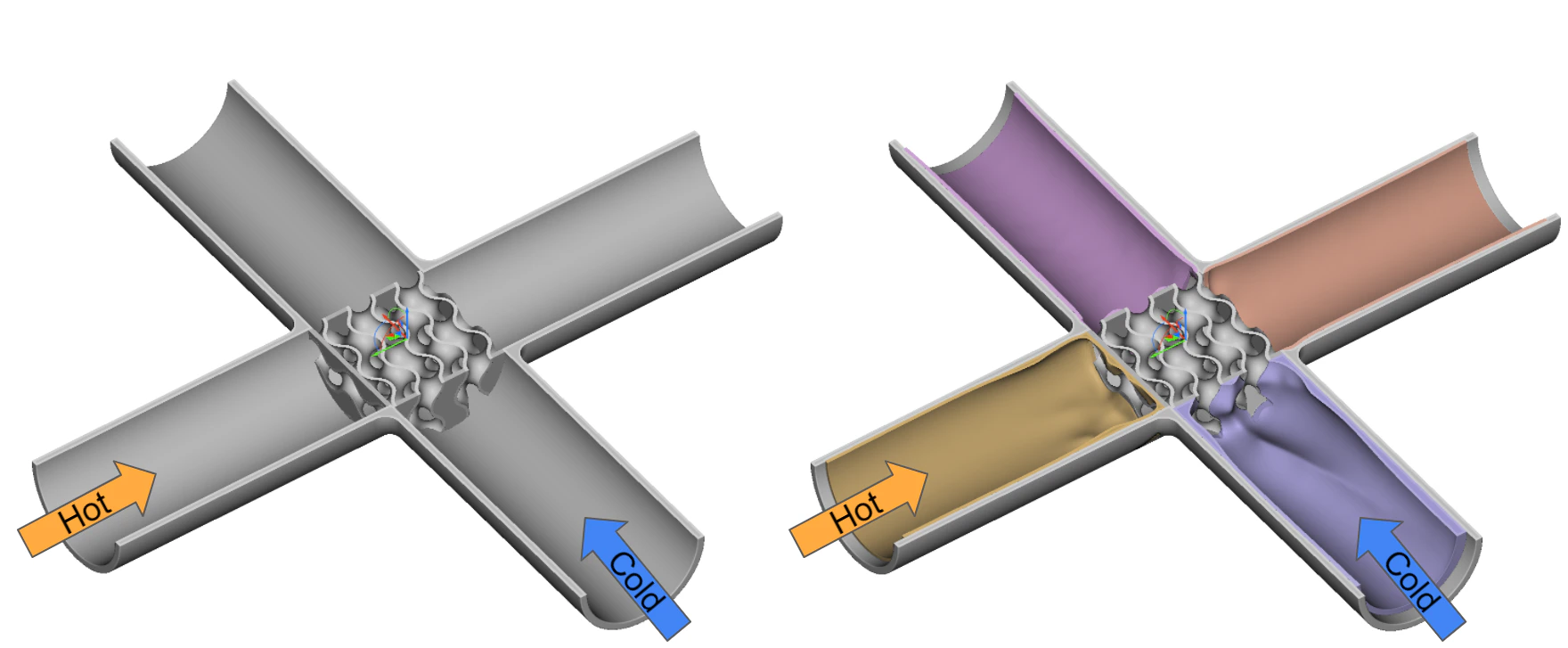
Procedure:
The steps outlined below focus on the Cold Inlet section, the same blocks and methods are utilized for the other plumbing sections. The majority of the blocks used can be seen in Image #2 below.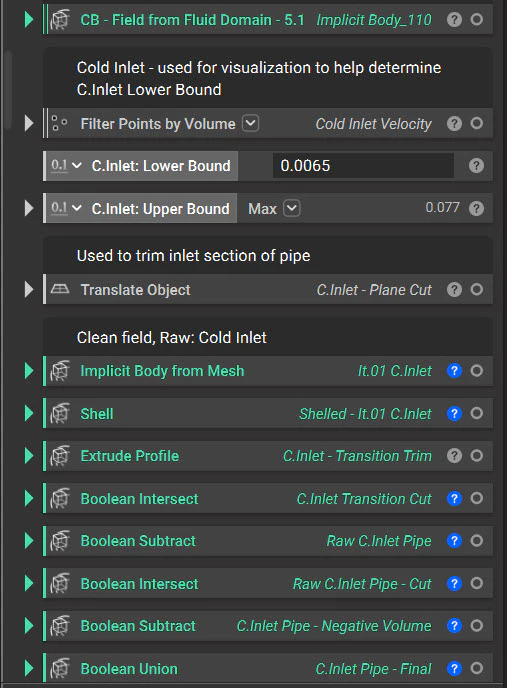
1. Import Scalar Field
Import the CSV file created from our CFD results of the cold fluid only.
2. Import Custom Block to generate the initial ‘raw’ implicit of the updated fluid domain
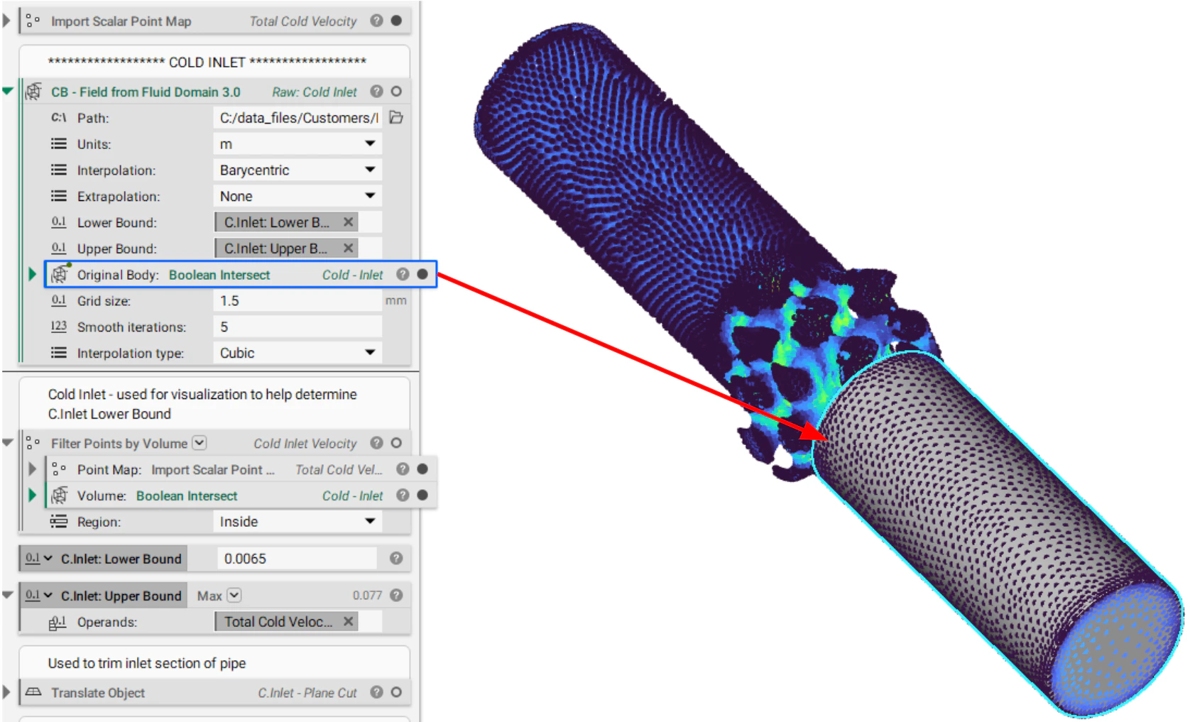
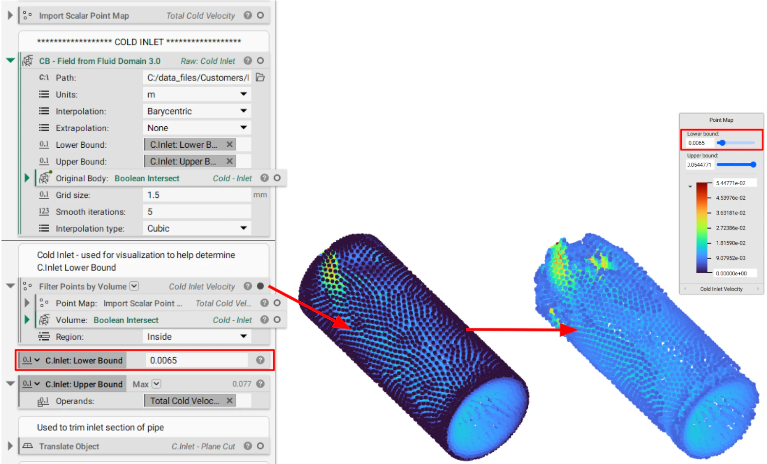
This step takes the workflow established in the How to use nTop to help design plumbing domains article and turns it into a custom block (CB). Image #4 below shows this CB with the inputs filled in. This step focuses on the Lower and the Upper Bounds. The final product of this step (i.e. the CB below) is in Image #5. The resulting implicit body can be used for further CFD analysis and/or generate a new solid plumbing geometry that attaches the HEX core.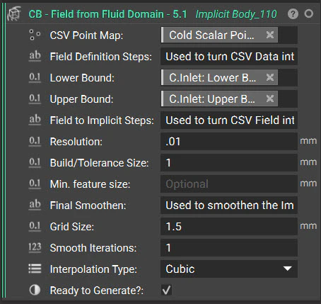

Note: This is a great time to check the Simplify option as we are not using this mesh as an input into our Remesh block and are just creating an implicit from it. Checking this box reduces the total element count thereby reducing overall file size.

3. Working with the new implicit
Now that we have our cleaned updated fluid domain there are two main avenues we take. One is generating our ‘final’ solid piping geometry and the second is generating our ‘final’ fluid domain for further CFD evaluation. At least one Shell operation is required and the rest are achieved with mostly a combination of Boolean Unions, Subtractions, and Intersections. As this step is somewhat specific to the application and can be quite involved, it is not broken down into detail but instead can be viewed in the video below.
That should do it! If you followed the steps above you should now know how to reshape your plumbing geometry to help increase performance.
If you still have questions the support team would be happy to help you.
Download the Example files:
Files include two CSV files (Cold_Velcoity and Hot_Velcoity) as well as the nTop file shown in the images and video above. All the steps above the section ‘Cold CFD Import’ are covered in previous training.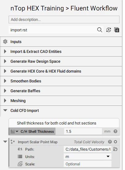
Note: The Meshing steps in the nTop file above, while still sufficient, are no longer the preferred route. Using the Mesh from Implicit Body by Voxel block into a Remesh block is the preferred route found at the bottom of the nTop file.
- How to export variables in CSV format from Ansys CFD Post
- How to display and view imported CFD data
- How to use nTop to help design plumbing domains