Objective:
Learn how to use the Displacement Restraint block and apply the prescribed displacementApplies to:
- Static Analysis
Procedure:
Before we start, Prescribed displacement is supported only in Static Analysis and is not supported for Topology Optimization. This article uses Displacement Restraint to apply prescribed displacement, but you can also use the Cylidrincal Restraint and Point Restraint blocks.This article uses Simulation/Optimization and both of them in nTop have two requirements: FE Mesh and Boundary Conditions (BCs). Follow the instructions in the links below to prepare your model for simulation.FE MeshBoundary Conditions (BCs)
- We start with the Simulation Model required for our simulation. I recommend checking our surface meshing best practices (What are surface meshing best practices?) to understand different parameters.
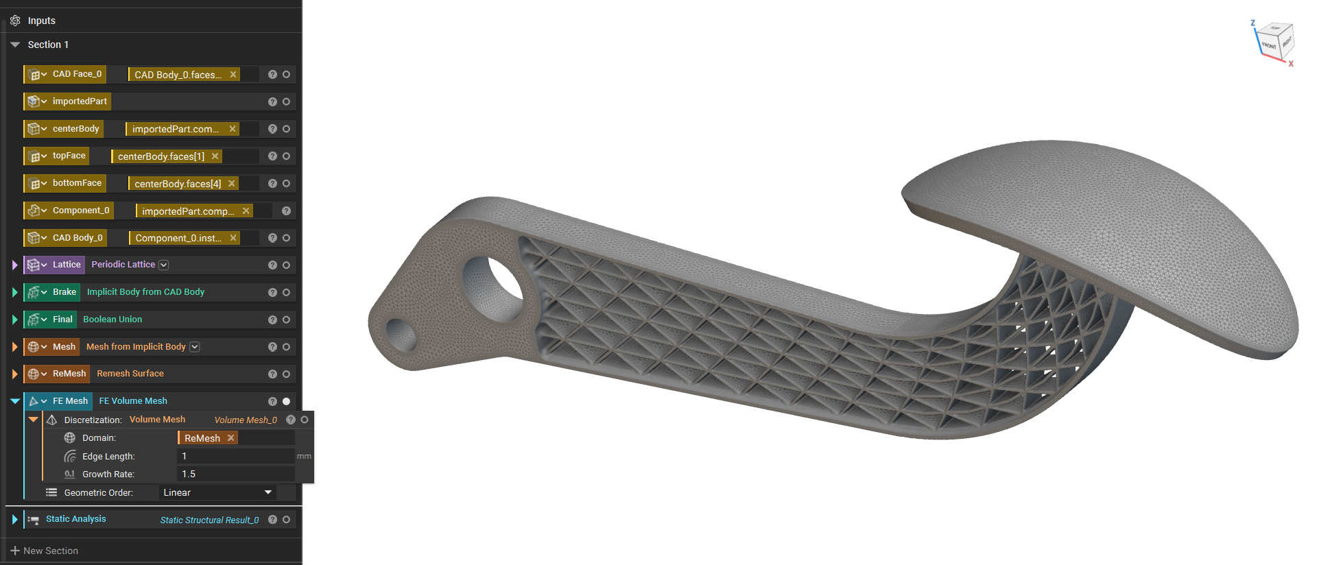
- The next step is to add two Displacement Restraintblocks, we will use one to fix the nodes of one end and apply the prescribed displacement in the other one.
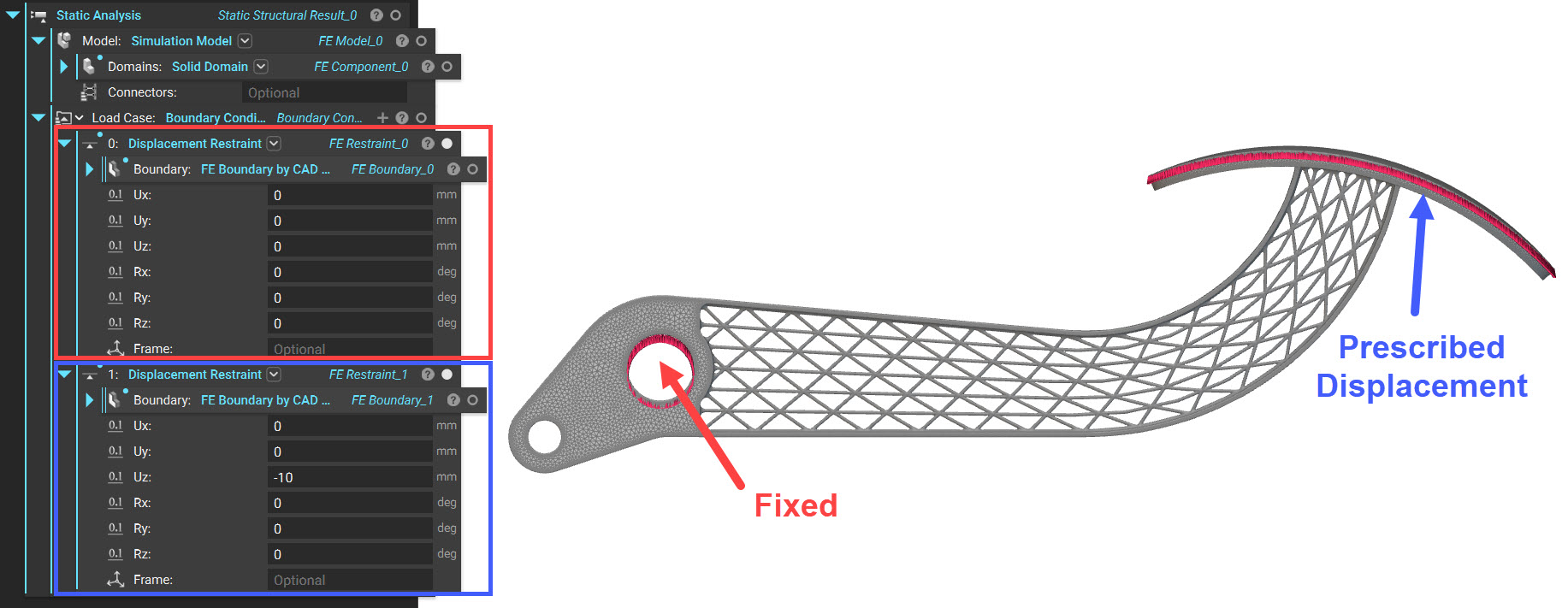 The only difference in using this block for Prescribed Displacement is that you must enter the input value corresponding to the input you wish that represents how far you are moving the selected nodes/faces in that direction. The block will then apply the displacement value to all selected boundaries attached to the specified geometry.
The inputs of the Displacement Restraint block are:
The only difference in using this block for Prescribed Displacement is that you must enter the input value corresponding to the input you wish that represents how far you are moving the selected nodes/faces in that direction. The block will then apply the displacement value to all selected boundaries attached to the specified geometry.
The inputs of the Displacement Restraint block are:
- Boundary: The FE Boundary entities containing the nodes to restrain.
- Ux: Translational restraint along the x-axis.
- Uy Translational restraint along the y-axis.
- Uz: Translational restraint along the z-axis.
- Rx: Rotational restraint along the x-axis.
- Ry: Rotational restraint along the y-axis.
- Rz: Rotational restraint along the z-axis.
- Frame: The reference frame for the input translational and rotational components. If a Frame is not specified, the components are in the global coordinate system.
Note: The displacement input value will not be divided by the number of nodes in the boundary selected.
- Run the Static Analysis (How to run a static analysis), and you can see that the nodes selected for prescribed displacement have moved the input -10mm in the Z direction.
 And that’s it! You have successfully applied prescribed displacement.
Do you still need help? Contact the support team, and we’ll be happy to help!
And that’s it! You have successfully applied prescribed displacement.
Do you still need help? Contact the support team, and we’ll be happy to help!