This article uses Simulation/Optimization and both of them in nTop have two requirements: FE Mesh and Boundary Conditions (BCs). Follow the instructions in the links below to prepare your model for simulation.FE MeshBoundary Conditions (BCs)
Question:
How can I simulate a pipe with internal pressure?Applies to:
- Simulation
Answer:
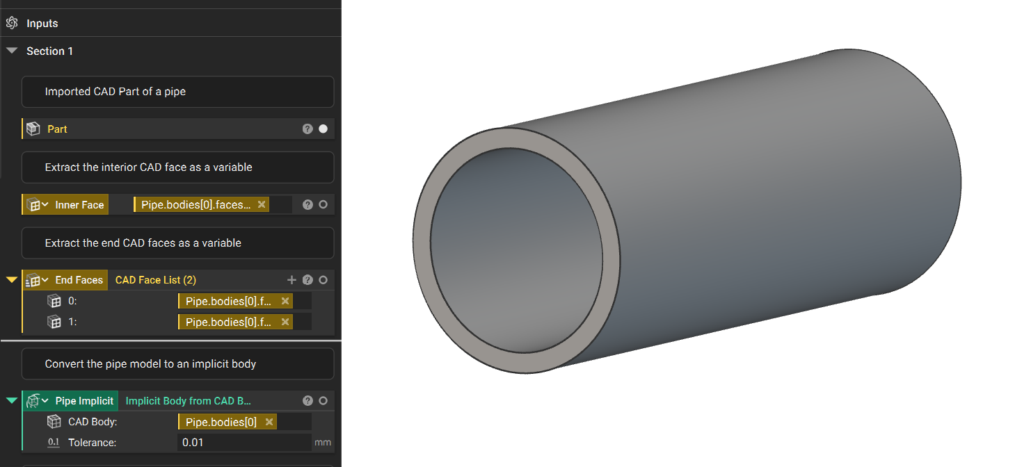
- **Setup:**The initial setup shows our imported pipe as well as the CAD Faces we’ve defined.
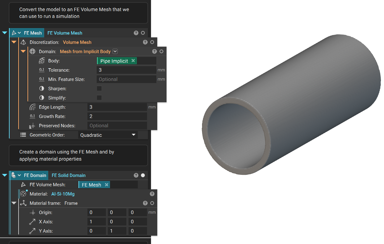
- **Meshing:**Next, the FE Volume Mesh and FE Domainare created to apply material properties.
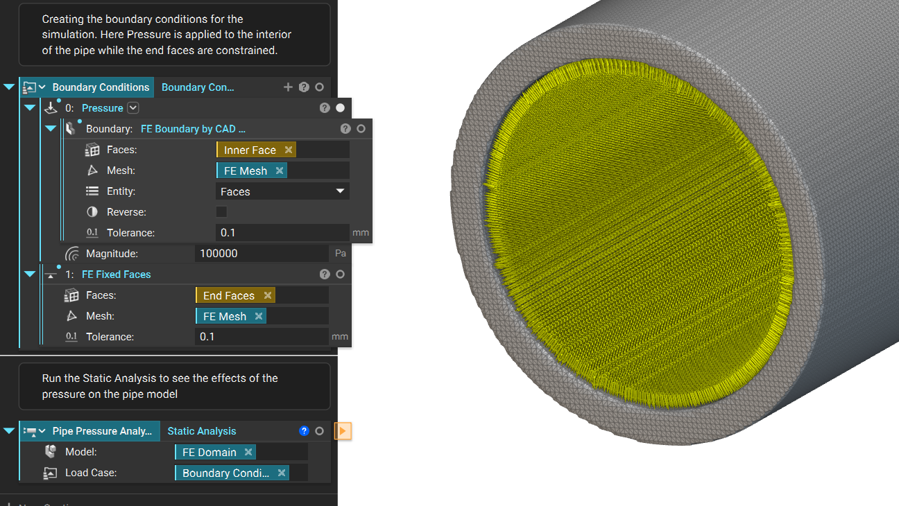
- Boundary Conditions: To finish the Static Analysissetup we apply the Boundary Conditions and then run the analysis.
- **Analysis:**Using the Deformation scale slider, you can see the effects of the Pressure on the pipe.
 And that’s it! You’ve successfully setup an internal pressure analysis.