Question:
What are the options for simulating lattices?Answer:
There are three main methods for simulating lattices in nTop. They are using Solid Elements, Beam Elements, or Homogenization. The pros and cons of each method are listed in the table with an example workflow below.| Type | Pros | Cons |
|---|---|---|
 |
|
|
 |
|
|
 |
|
|
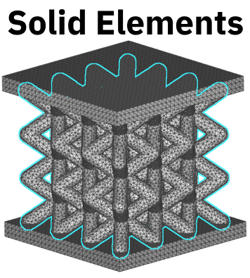
Solid Elements
Solid elements are volumetric finite element mesh of the entire lattice structure.- A finer mesh is required to capture the detail of the lattice
- Use Remesh Surface block after Mesh from Implicit Body
- Volume Mesh block may fail; if so, you can repair the mesh through Mesh from Implicit Body and Remesh Surface or use the slower, more robust, Robust Tetrahedral Mesh.
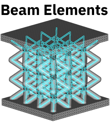
Beam Elements
Beam elements are finite element nodes along lattice vertices connected by lattice beams. This method greatly reduces the number of elements from a typical volume mesh but ignores certain mechanical behavior like edge effects and stress concentrations in the lattice. FE nodes will be placed at the endpoints of each beam, along with node(s) and the subdivisions of the beam. You can choose the number of subdivisions as input to the FE Lattice Mesh block, which will be arrayed as demonstrated in the image below.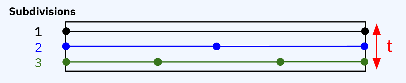 Set up a Lattice Domain in Simulation Model.
- Use Trim Lattice to ensure the lattice elements lie within the volume of the Lattice Structure.
- If you get a warning about short lattice beams, use Collapse Lattice Vertices with a threshold much lower than the unit cell size.
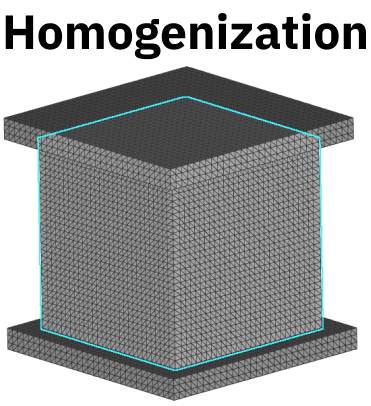
Homogenization
To create a homogenized simulation, run a Solid FEA simulation on a single unit cell of the lattice, and generate effective material properties of the unit cell. Next, run a second Solid FEA simulation on the bulk lattice structure volume using the effective material properties (from the first simulation). Use Solid Domain with the Material chip from the Homogenization block.- Works best with many unit cells
- Good for comparing different lattice types
Comparison
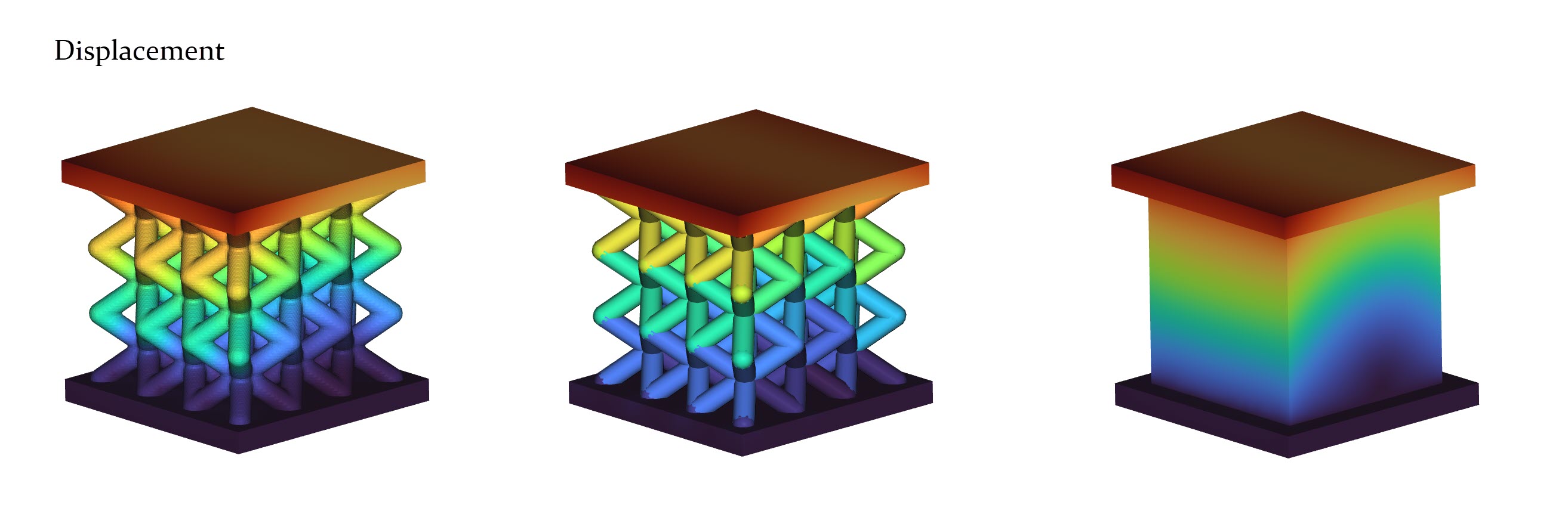
To compare these methods, we’ve created a BCC Lattice between two panels. Look for the download of this Case Study at the bottom of this article.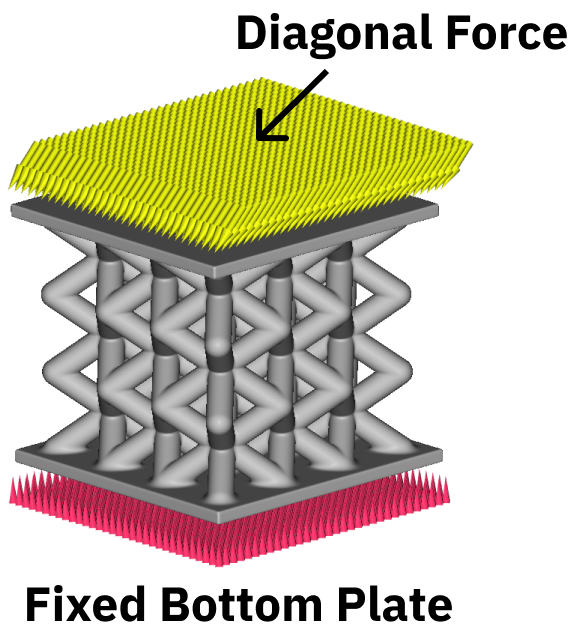 The images below represent a direct comparison in Displacement values and Von Mises Stress values. The images are in the same order as above (Solid Elements, Beam Elements, and Homogenization). Scroll below to see the range of values.
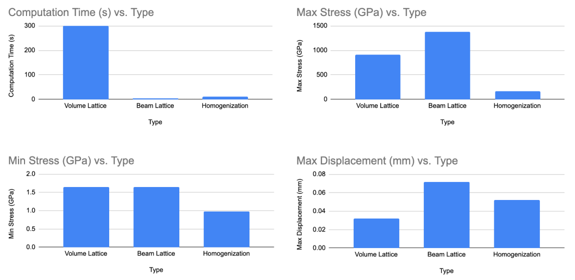
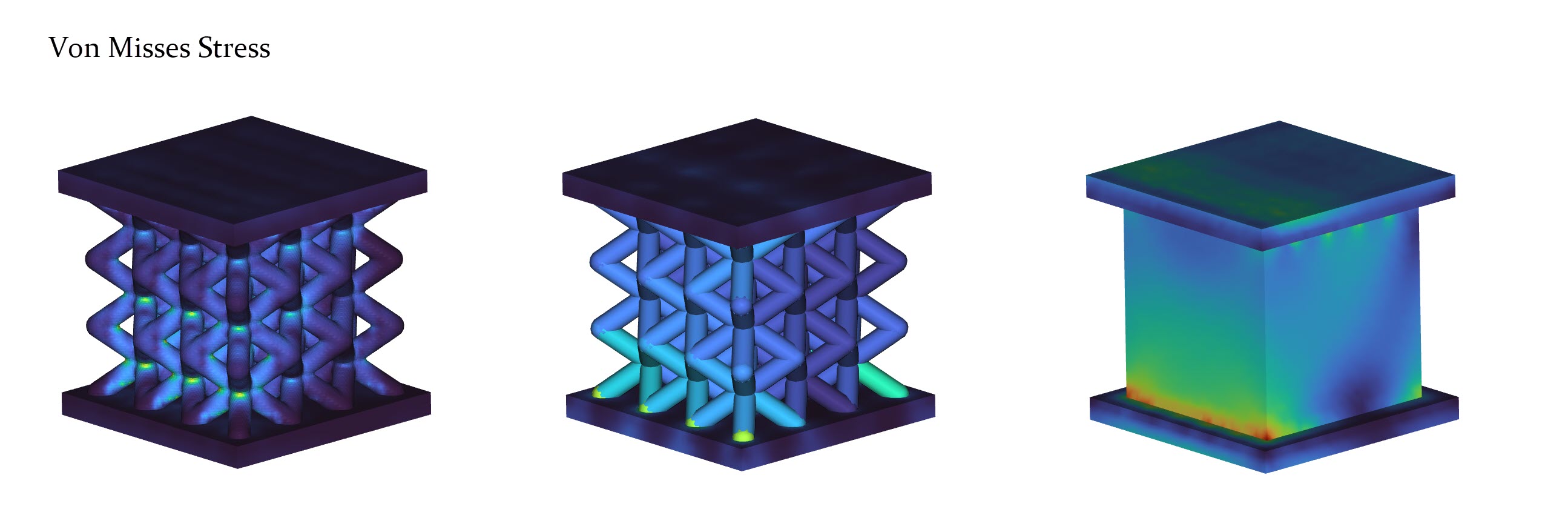 Below is a direct comparison of the three methods: computational time, stresses, and displacement.