Objective:
Learn how to use the block CFD Boundary on FE Mesh to create named boundaries and export them with your FE Mesh. Setting up CFD boundary zones allows you to modify the underlying geometry in nTop without having to manually update the boundary conditions in the CFD application, thereby enabling automated design workflows.Applies to:
- Ansys Fluent
- nTop 3.4+
Procedure:
1. Start with an FE Volume Mesh of your design. 2. Choose boundaries-
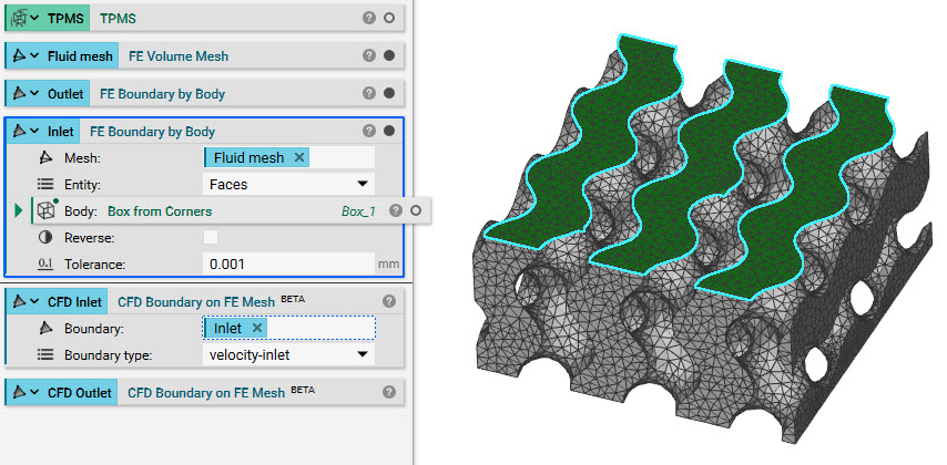
- Decide what boundaries you need to define for your analysis. Use either FE Boundary by Body or FE Boundary by Floodfill to choose the areas on your mesh.
- Make sure to use the Faces as the entity in your selection, since the CFD Boundaries can only be applied to volumetric elements
- Decide what boundaries you need to define for your analysis. Use either FE Boundary by Body or FE Boundary by Floodfill to choose the areas on your mesh.
-
- Add a CFD Boundary on FE Mesh block (make sure to have beta blocks turned on)
- Insert one of the boundary selection blocks into the FE set field
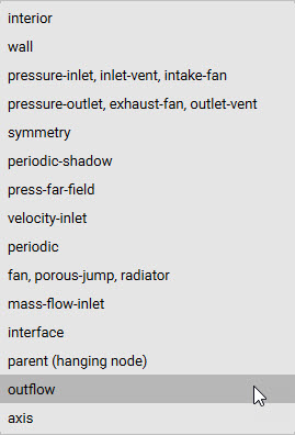
- Choose the most accurate CFD Boundary type for your selection
- Add a CFD Boundary on FE Mesh block (make sure to have beta blocks turned on)
- Repeat this process for each selection
 4. Export Mesh and Boundaries together
-
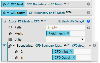
- Add in the beta block, Export FE Mesh to CFD to allow the FE sets to be exported with your mesh. To use this block, your FE Mesh needs to be an FE Volume mesh and not an FE Surface mesh.
- Insert the FE Volume Mesh
- Add the block CFD Boundary List into the Boundaries input. Insert your boundaries into the List
- Choose a path and save your file as a .msh
- Add in the beta block, Export FE Mesh to CFD to allow the FE sets to be exported with your mesh. To use this block, your FE Mesh needs to be an FE Volume mesh and not an FE Surface mesh.
 And that’s it! You’ve successfully created and exported CFD boundaries.
Are you still having issues? Contact the support team, and we’ll be happy to help!
And that’s it! You’ve successfully created and exported CFD boundaries.
Are you still having issues? Contact the support team, and we’ll be happy to help!