Objective:
How to use a CAD Face in a boundary condition.Applies to:
- Boundary Conditions
Procedure:
Note: If you are running into the error shown below, then you most likely have a CAD Face that isn’t associated with a mesh. Continue reading below to solve this issue.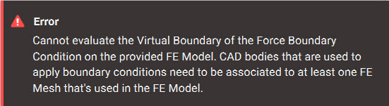
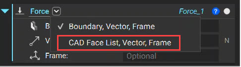
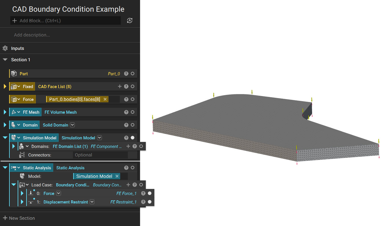
- Select the CAD Face List overload in the boundary condition block.
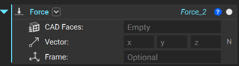
- Use the CAD Face directly as an input or the CAD Face List block to select multiple CAD faces for scoping your boundary condition.
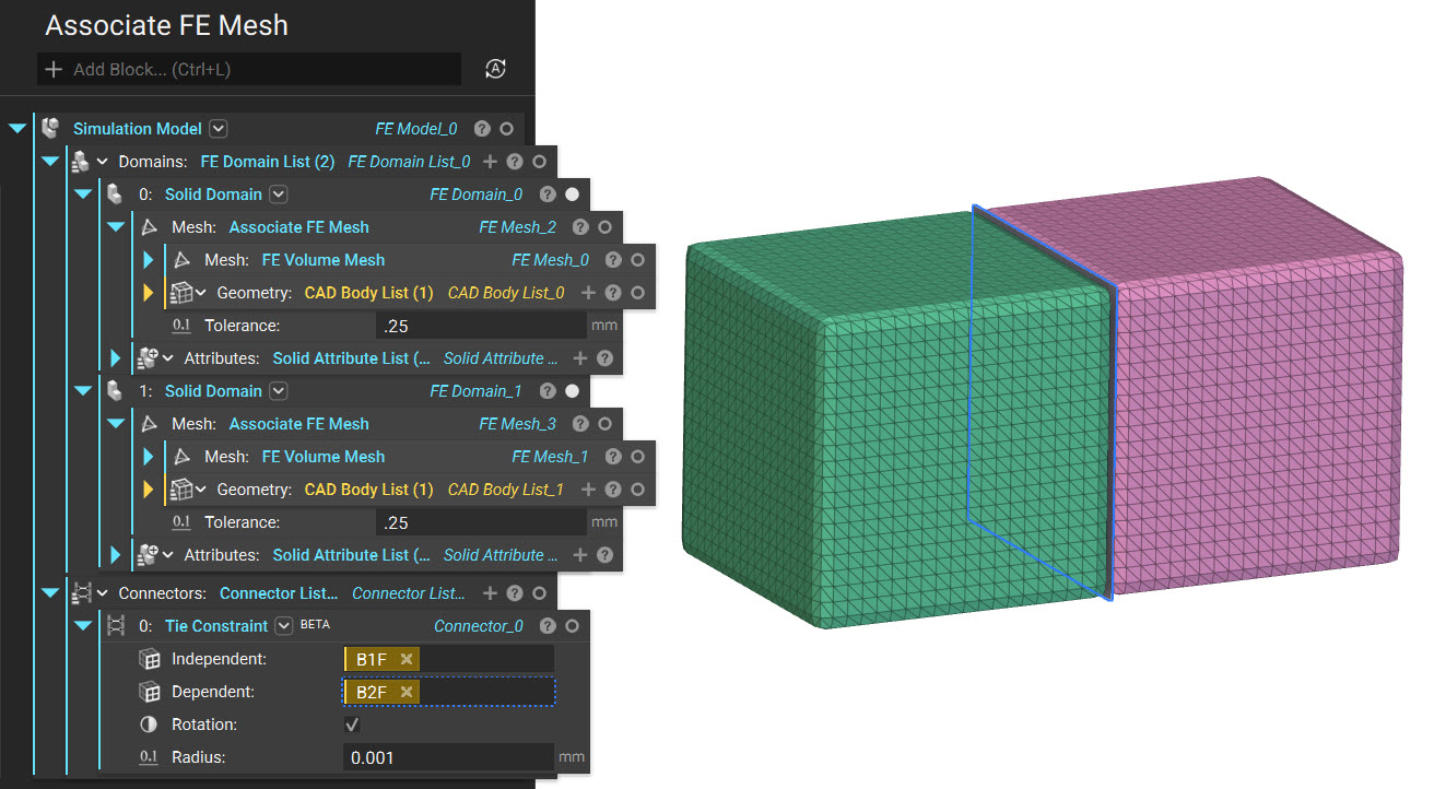
- Associate the FE Mesh with the CAD body containing the CAD faces selected in the above step.
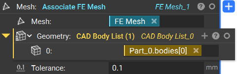
- Mesh: The FE Mesh is to be associated with the CAD Body.
- Geometry: CAD bodies from which the boundary CAD faces are scoped.
- Tolerance: Tolerance is the Maximum distance between selected mesh elements and the chosen topology.
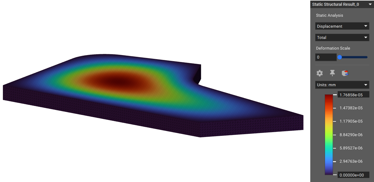 And that’s it! You’ve successfully used CAD face to scope a boundary condition.
Are you still having issues? Contact the support team, and we’ll be happy to help!
And that’s it! You’ve successfully used CAD face to scope a boundary condition.
Are you still having issues? Contact the support team, and we’ll be happy to help!